REPORT
On laboratory work №4
On the discipline “Electrical machinery”
Specialty: 5B071800- Electrical Power Engineering
Done by: Shaimuradov E. Group: EPEe-15-10
Checked by: Abdulaev Z.A.
_________ ___________ “___” __________ 2017
(score) (signature)
Laboratory work №4. Research of an asynchronous electric motor with a squirrel-cage rotor
Purpose of work:
Study of the operating properties of a three-phase asynchronous electric motor by removing the corresponding experimental characteristics.
Program of work:
1. To study the scheme for the investigation of an induction motor with a squirrel cage rotor (hereinafter referred to as AD)
2. Investigate the motor in short circuit mode.
3. Investigate the engine in idle.
4. Remove the performance of the engine by the direct load method.
5. According to the experiments of idling and short circuit, calculate the parameters of the engine, build a replacement circuit.
6. Conduct experimental data processing, compile a report and make a conclusion
Explanations for work
In the laboratory work the following modules are used:
- Stand Power Module (SPM);
- power module (PM);
- module of power (MP);
- module of the frequency converter (MFC);
- power meter module (PMM);
- Measuring module (MM).
- module of additional resistance 1(MAR)
- module of additional resistance 2 (MAR)
Before conducting laboratory work, you must bring the modules to their original state:
- switch SA1 of the module MAR1 set to the position "∞".
- switch SA1 of the module MAR2 set to the position "∞".
The investigated asynchronous motor is a part of the electric machine unit, which includes the actual M1 engine under investigation, the load generator - the DC machine M2, the pulse speed sensor M3
1. The experience of a short-circuit of an asynchronous motor
The short-circuit test is carried out at a fixed and reduced voltage, at which the stator current is approximately equal to the rated current of the stator
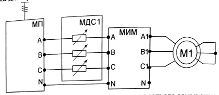
Figure 1. Scheme for carrying out idle and short circuit experience
Braking of the engine is carried out by installing a metal rod in the hole of the coupling half.
Lowering the voltage is achieved by including an additional resistance in the stator circuit.
The experiment is carried out in the following sequence:
- turn on circuit breakers QF1, QF2 - apply voltage to the induction motor;
- Switch SA1 MAR1 to introduce resistance into the stator circuit until the stator is approximately equal to the rated current of the stator.
Record the experience data in Table 1.
| Data of experience | Calculated data | ||||||||||
| U1фк | I1фк | P1фк | cosφ | P1k | ∆Pel1 | ∆Pcт | Pem,k | Mem,k | Zk | rk | xk |
| V | A | W | W | W | W | W | N*m | Ω | Ω | Ω | |
| 1,3 | 0,051 | 0,192 | 99,38 | 1,69 | 42,93 | 0,29 | 170.46 | 9.36 | 170.2 |
After carrying out the test, it is necessary to switch off automatic breakers QF1, QF2,bring the modules to their original state, remove the metal rod from the electric machine unit.
According to the data of the short-circuit test, determine the starting current, the starting torque at
Experience of idling the induction motor.
Investigations of the engine in the idle mode are carried out for a single value of the impulse equal to the rated value, and it is possible to estimate the value of the no-load current, as well as the loss in steel at the rated voltage.
The circuit for conducting an idling test is shown in Fig. 1
The experiment is carried out in the following sequence:
- turn on circuit breakers QF1, QF2accordingly SPM and PM;
- switch SA1 of the module MAR1 set from the position "∞" to position "" voltage take the value which equal to nominal, asynchronous motor starts.
Record the experience data in Table 2.
| Data of experience | Calculated data | |||||||
| U1фн | I10 | P1ф | ω | P10 | cosφ10 | ∆Pel1 | ∆Pст | I10* |
| V | A | W | W | W | W | W | N*m | |
| 387,6 | 1,28 | 0,052 | 129.9 | 0,183 | 91,93 | 1,66 | 0,92 |
After carrying out the test, it is necessary to switch off automatic breakers QF1, QF2,bring the modules to their original state
Conducting the working characteristics
The circuit for conducting the working characteristics is shown in Fig. 2
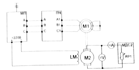
Figure 2. Circuit for conducting the working characteristics
The asynchronous motor is connected directly to the frequency converter.
The DC winding of the DC motor is powered from the “220V” power module terminals.
The anchor chain of the DC machine is connected to the resistance SA1 MAR2
A frequency converter is used to measure the current, the frequency of the stator output voltage, the motor power and the torque of the asynchronous motor.
The current of the anchor and the voltage at the anchor are measured with the help of MM devices.
The current value of the speed of rotation n of the agregate is monitored on the PM indicator.
The experiment is carried out in the following sequence:
- turn on circuit breakers QF1, QF2 of SPM and PM modules;
- setup the frequency converter
- Switch SA1 MAR1 to introduce resistance into the stator circuit until the stator is approximately equal to the rated current of the stator.
Installing SA1 module FC in the extreme position to start the induction motor. Set the output frequency to 50 Hz
With switch SA1 MAR2, reducing the resistance, increase the load GDC until the anchor current GDC reaches the nominal value.
Do not upload motor more than this value.
Record the experience data in Table 3.
Table 3
| From the asynchronous motor side | |||||||||||||
| Data of experience | Calculated data | ||||||||||||
| I1ф | P1фк | n | cosφ1 | U1 | ∆Pel.st | ∆Pem | s | ∆Pel.rotor | Pmech | ∑∆P | P2 | Mem | η |
| A | W | Turn/ min | V | W | W | W | W | W | W | N*m | % | ||
| 1.25 | 0.12 | 78.02 | -12.75 | 0.099 | -1.18 | 4.73 | 158.26 | 12.74 | 0.65 | 1.06 | |||
| 1.27 | 0.128 | 392.2 | 76.69 | -3.29 | 0.157 | -0.5 | 4.5 | 157.61 | 14.39 | 0.91 | 8.6 | ||
| 1.29 | 0.132 | 76.69 | 5.59 | 0.2 | 1.118 | 4.72 | 159.13 | 14.87 | 1.105 | 8.54 | |||
| 1.32 | 0.135 | 393.3 | 76.69 | 7.58 | 0.2 | 1.895 | 4.73 | 160.01 | 1.3 | 10.11 |
Table 4
| From the DCG side | |||||||
| Data of experience | Calculated data | ||||||
| Ia | Ua | Mem | Iao | M0 | M2 | P2 | η |
| A | V | N*m | A | N*m | N*m | W | % |
| 1.11 | 113.2 | 0.65 | 1.25 | 0.247 | 0.897 | 116.6 | |
| 1.3 | 114.5 | 0.91 | 1.28 | 0.234 | 1.144 | 138.17 | |
| 1.3 | 1.105 | 1.32 | 0.234 | 1.339 | 152.05 | ||
| 1.4 | 117.4 | 1.3 | 1.4 | 0.1275 | 1.52 | 163.38 |
After carrying out the test, it is necessary to switch off automatic breakers QF1, QF2,bring the modules to their original state
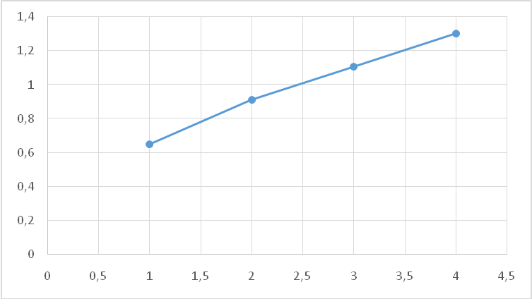
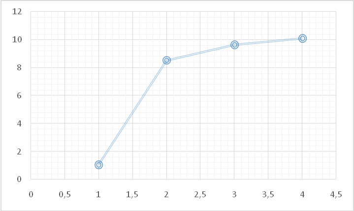
Dependence of Mem on P2
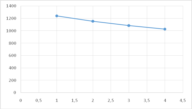
Dependence of n on P2
Dependence of η on P2
Listofreferences
1 Копылов И.П. Электрические машины.-М.: Высшая школа, Логос, 2000. -607 с.
2 Брускин Д.Э., Зорохович А.Е., Хвостов В.С. Электрические машины. Ч. 1,2. -М.: Высшая школа, 1987.
3 Копылов И.П. Электрические машины.-М.: Энергоатомиздат, 1986.-360 с.
4 Вольдек А.И. Электрические машины.-Л.: Энергия, 1978.-832 с.
5 Костенко М.П., Пиотровский Л.М. Электрические машины. Ч.2 Машины переменного тока.- Л.: Энергия, 1973. - 412 с.