Informal step by step for setting up universal and revolute kinematic joints in Femap 2022.1
Step 1:
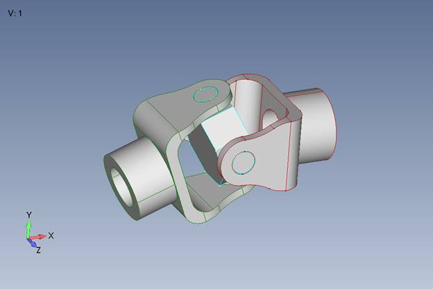
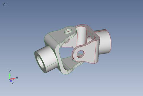
Import “u_joint.x_t” Parasolid file
Step2:
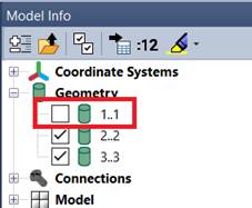
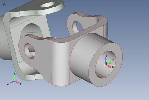
Hide the solid in the middle
Step 3:
Need to create two coordinate systems with the X – axis aligned from hole to hole of each clevis. This is for the universal joint element definition.
НеобходимосоздатьдвесистемыкоординатсосьюX, выровненной от отверстия к отверстию каждойвилки. Этонеобходимодлязаданияуниверсальногошарнирногоэлемента.
Step 3a:
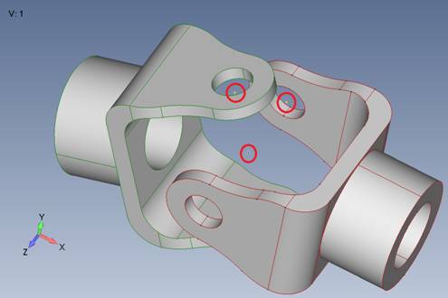
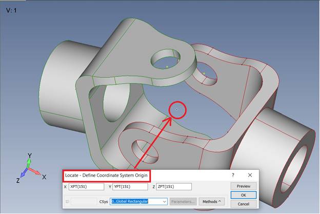
Create a point at the origin 0, 0, 0 for the center of rotation for the u joint. We will also use this for locating coordinate systemorigin and axes. Create two more points at the center of the holes on the clevis.
Создайте точку в начале координат 0, 0, 0 для центра вращения u-образного шарнира. Мы также будем использовать это для определения местоположения начала координат и осей системы координат. Создайте еще две точки в центре отверстий на зажиме.
Geometry – Point – (0;0;0)
Geometry – Point – (Center)
Step 3b:
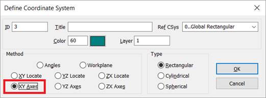
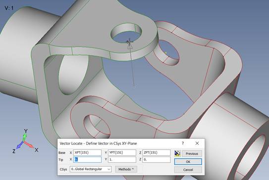
Use the reference points made in the previous step to orient new coordinate systems defined by XY axes.
Model – Coord Sys…
Orienting X direction -

Orienting Y direction-
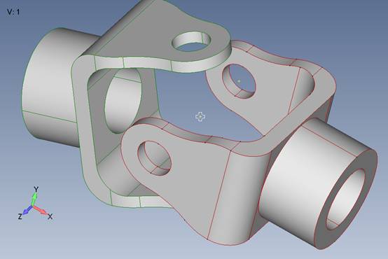
After coordinate system is created –
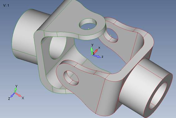
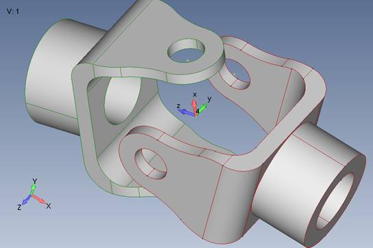
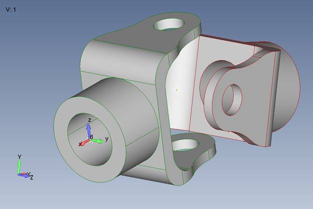
Repeat this step to create the coordinate system for the other clevis. (Finished coordinate system shown with the first one hidden for viewing purposes.) Notice the different in X axis orientation.
Step 4:
Create a kinematic connection for u joint.
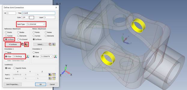
Step 4a:
Set the joint type to “Universal”. Set the Reference Attachment as “Surface”. Select the four surfaces that make up the holes of the clevis on the right. Change Orientation 1 to coordinate system 3 created previously. Notethat the X – axis of this coordinate system is aligned with the axis of the holes.
Step 4b:
Repeat for “Motion Attachment” side. Note that orientation 2 uses Csys 4.
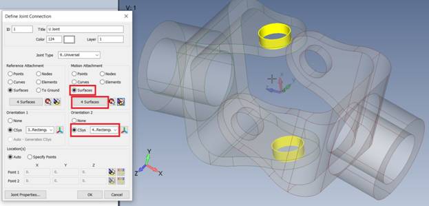
We now have our universal joint kinematic connector setup. (Both coordinate system hidden for viewing)
Step 5:
Create the revolute joint at each end of the part.
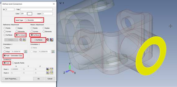
Step 5a:
Create another Kinematic Connector, this time set the type to “Revolute”. Under Reference Attachment select “To Ground” meaning that this part of the assembly will be able to rotation about a grounded point. In Motion Attachment, use “Surfaces” and select the cylindrical surface on the back face of the clevis. Leave the Orientation and Location set to Auto. Femap will automatically create the orientation coordinate system with the X – axis aligned to the rotation axis.
After joint is created:
Step 5b:
Repeat this with the other side.
You should now have 1 universal joint and 2 revolute joints.

Step 6:
Create the Kinematic Driver Load.
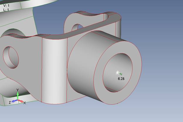
Use Model > Load > Kinematic Driver…, label the load set, choose the load type as “Enforced Rotation”. Set the value to 6.28 radians equating to 360 degrees or one full revolution.

Select the first revolute joint created. (Notice coordinate system is hidden for viewing purposes)
Step7:
Mesh the parts of geometry and not the one that is hidden.
Step 8:
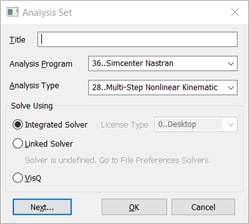
Create analysis set.
Step 8a:
Create a 402 solution
Step 8b:
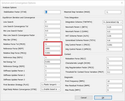
Open the Control Options and jump in the “Iteration and Convergence” dialog. Set the following parameters as shown. This is to help get the model converge since there isn’t much to counteract motion.This is just a simple use case model.
Step 8c:
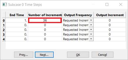
Set the time steps to 36 equating to a result set at every 10 degrees of rotation.
Step 8e:
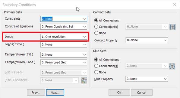
Note that the driver load is not time assigned so the solver will auto step the load proportionally to the number of increments. Also note that a constraint set is not needed for this analysis. The revolute “to ground” joints will create a grounded node that will write to the input file as a permanent constraint.
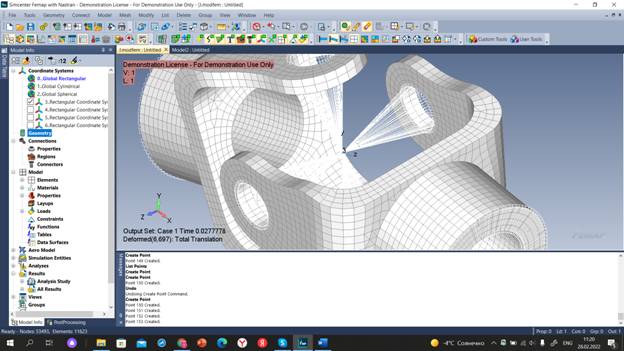
Step 9:
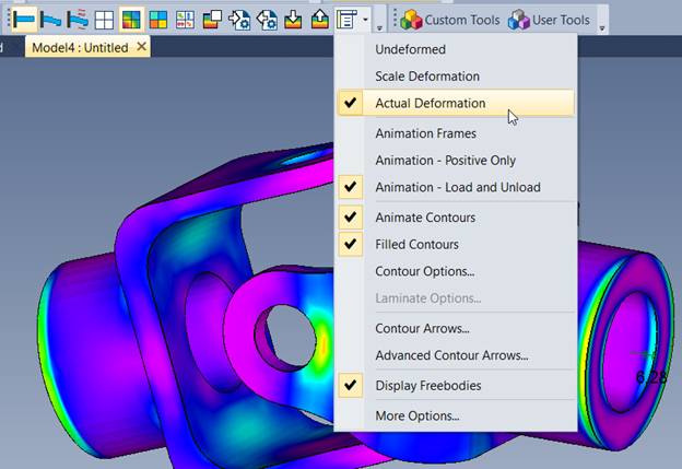
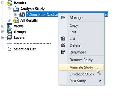
Once analysis has finished, set the contour view to Solid Von Mises and switch to “Actual Deformation” then use the analysis case under Results in the model info tree and Animate Study.