Заходим на сайт www.fips.ru и спускаемся в самый низ, ищем кнопку «Ссылки»;
На открывшейся странице ищем кнопку «Зарубежные БД» (БД – базы данных);
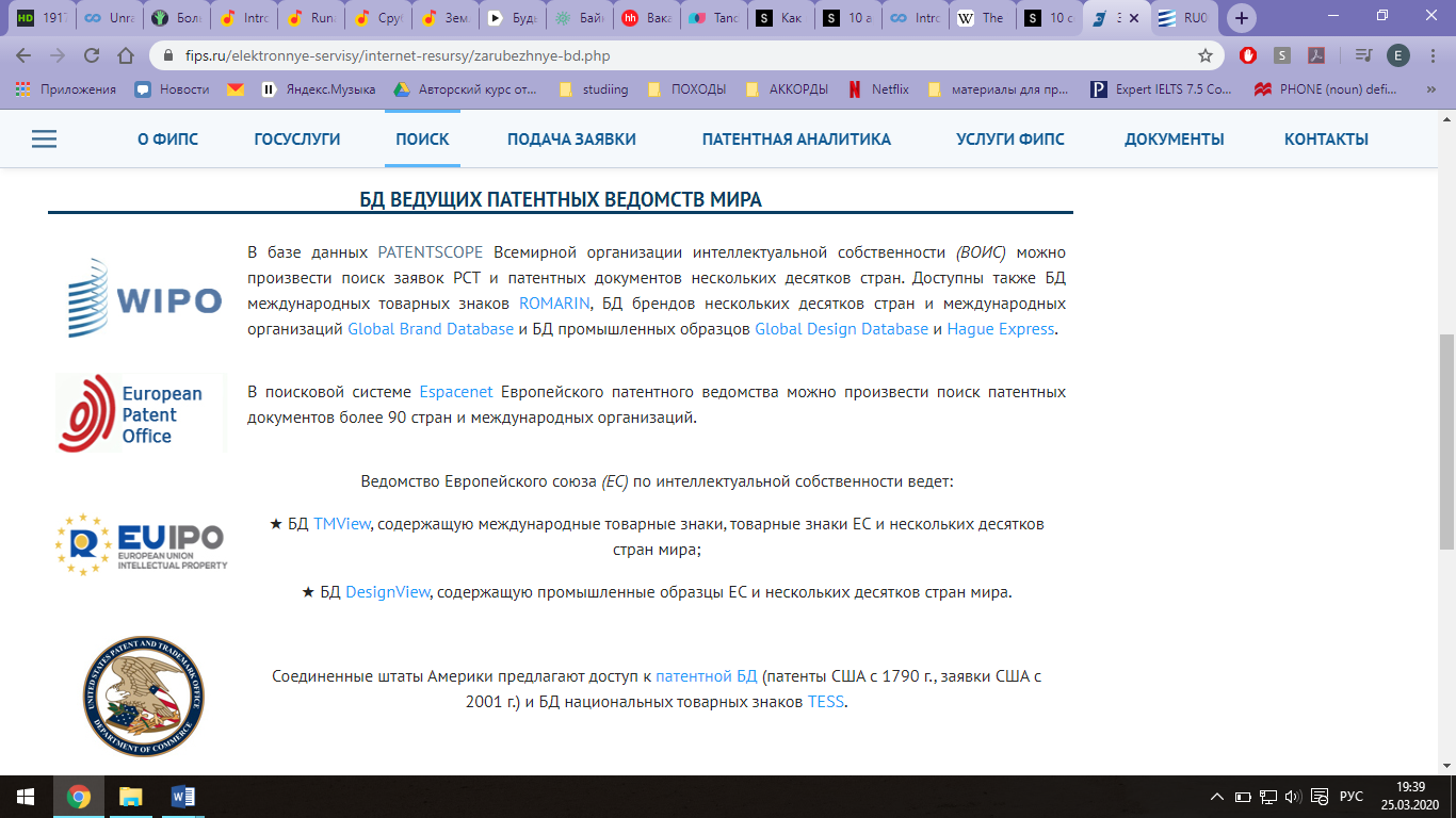
Спускаемся ниже, где изображены логотипы сайтов для поиска зарубежных патентов, ищем в разделе «БД ведущих патентных ведомств мира» ссылку «PATENTSCOP» (Всемирная организация интеллектуальной собственности (ВОИС)) нажимаем;
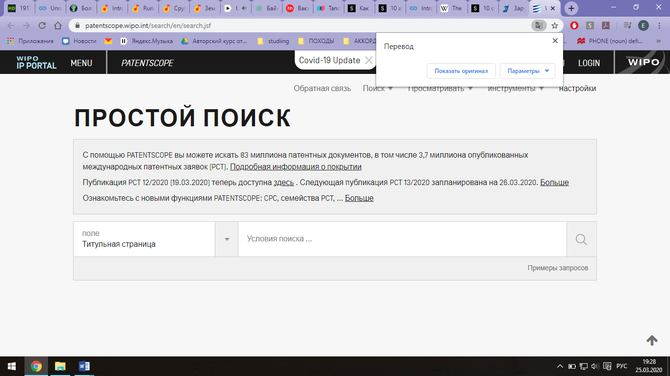
Открывается новая страница с адресом www.patentscope.wipo.int, при необходимости можем сменить язык на русский.
Листаем ниже, в строке «Искать термины» набираем ключевое слово поиска (например, «стол»), нажимаем на поиск;
Когда сайт выдает варианты найденных изобретений, в шапке необходимо найти кнопку "Просмотреть" и нажать на выплывающее меню (на стрелочку) и выбрать из списка "All+image", чтобы увидеть не только текст изобретений, но и чертежи;
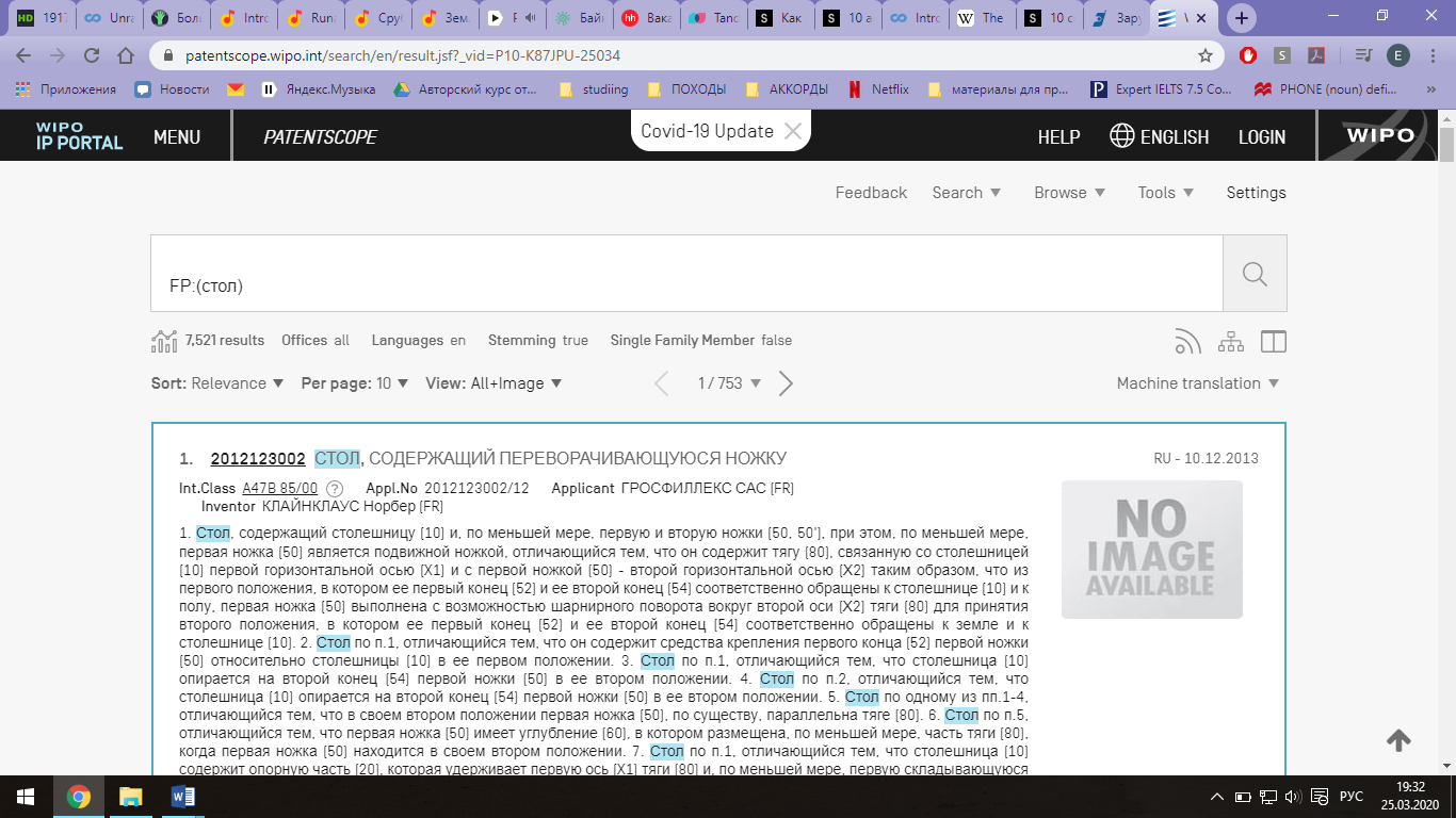
Выбираем подходящий патент, нажимаем на номер публикации (например, 0000109040), открывается страница патента, смотрим разделы в шапке страницы «Формула изобретения», «Чертежи», «Описание», «Нац. библиограф. данные», можем сохранить в формате PDF.
Пример найденного патента:
Первая вкладка «National biblio. Data»:
OfficeRussian Federation
Application Number2010154412/13
Application Date18.02.2011
Publication Number0000109040
Publication Date10.10.2011
Grant Number
Grant Date10.10.2011
Publication KindU1
IPC
E04G 1/32
E04G 25/00
B27B 21/00
InventorsГерасимов Александр Петрович (RU)
Title
(RU) МНОГОФУНКЦИОНАЛЬНЫЙ ТРАНСФОРМИРУЕМЫЙ СТОЛ-КОЗЛЫ(ВАРИАНТЫ)
Abstract
(RU)
1. Многофункциональный трансформируемый стол-козлы, содержащий основание, установленную на нем с возможностью съема основную столешницу, дополнительную столешницу, основание выполнено состоящим из двух рам, каждая из которых включает две опорные стойки, соединенные между собой связующими балками, каждая из опорных стоек одной из рам фланцевым соединением соединена со стойкой другой рамы с образованием Х-образных опор, при этом дополнительная столешница выполнена с возможностью установки ее в качестве полки на нижних балках рам основания. 2. Стол-козлы по п.1, отличающийся тем, что он содержит дополнительную опору, выполненную в виде двух вертикальных стоек, соединенных горизонтальными балками с возможностью соединения ее с нижней стороной основной столешницы. 3. Стол-козлы по п.2, отличающийся тем, что основная столешница выполнена с возможностью крепления с ее нижней стороны дополнительной опоры в случае ее неиспользования. 4. Стол-козлы по п.2, отличающийся тем, что он содержит тягу, выполненную с возможностью соединения одного из ее концов с нижней связующей балкой одной из рам основания, а противоположного ее конца - с нижней горизонтальной балкой дополнительной опоры, при этом дополнительная столешница выполнена с возможностью соединения одной из ее сторон с основной столешницей, а противоположной стороны - с дополнительной опорой. 5. Стол-козлы по п.1, отличающийся тем, что он содержит дополнительную опору для резки коротких бревен, выполненную с возможностью установки ее на основании с возможностью перемещения вдоль связующих балок для регулирования длины отрезаемых кусков, а также обеспечения полужесткого крепления бревна при распилке. 6. Стол-козлы по п.1, отличающийся тем, что опорные стойки рам основания снабжены опорными подпятниками. 7. Стол-козлы по п.1, отличающийся тем, что вертикальные стойки дополнительной опоры снабжены опорными подпятниками. 8. Стол-козлы по п.6, отличающийся тем, что опорные подпятники опорных стоек одной из рам основания выполнены откидными и снабжены смонтированными на них колесами для транспортировки устройства. 9. Многофункциональный трансформируемый стол-козлы, содержащий основание, установленную на нем с возможностью съема столешницу и дополнительную опору, основание выполнено состоящим из двух рам, каждая из которых включает две опорные стойки, соединенные между собой связующими балками, при этом каждая из опорных стоек одной из рам фланцевым соединением соединена со стойкой другой рамы с образованием Х-образных опор, дополнительная опора выполнена в виде двух вертикальных стоек, соединенных горизонтальными балками с возможностью соединения ее с нижней стороной основной столешницы. 10. Стол-козлы по п.9, отличающийся тем, что он содержит дополнительную столешницу, выполненную с возможностью установки ее в качестве полки на нижних балках рам основания. 11. Стол-козлы по п.9, отличающийся тем, что основная столешница выполнена с возможностью крепления с ее нижней стороны дополнительной опоры в случае ее неиспользования. 12. Стол-козлы по п.10, отличающийся тем, что он содержит тягу, выполненную с возможностью соединения одного из ее концов с нижней связующей балкой одной из рам основания, а противоположного ее конца - с нижней горизонтальной балкой дополнительной опоры, при этом дополнительная столешница выполнена с возможностью соединения одной из ее сторон с основной столешницей, а противоположной стороны - с дополнительной опорой. 13. Стол-козлы по п.9, отличающийся тем, что он содержит дополнительную опору для резки коротких бревен, выполненную с возможностью установки ее на основании с возможностью перемещения вдоль связующих балок для регулирования длины отрезаемых кусков, а также полужесткого крепления бревна при пилке. 14. Стол-козлы по п.9, отличающийся тем, что опорные стойки рам основания снабжены опорными подпятниками. 15. Стол-козлы по п.1, отличающийся тем, что вертикальные стойки дополнительной опоры снабжены опорными подпятниками. 16. Стол-козлы по п.14, отличающийся тем, что опорные подпятники опорных стоек одной из рам основания выполнены откидными и снабжены смонтированными на них колесами для транспортировки устройства. 17. Многофункциональный трансформируемый стол-козлы, содержащий основание, установленную на нем с возможностью съема основную столешницу, дополнительную опору, дополнительную столешницу и тягу, основание выполнено состоящим из двух рам, каждая из которых включает две опорные стойки, соединенные между собой связующими балками, при этом каждая из опорных стоек одной из рам шарнирно соединена со стойкой другой рамы с образованием Х-образных опор, дополнительная опора выполнена в виде двух вертикальных стоек, соединенных горизонтальными балками с возможностью соединения ее с нижней стороной основной столешницы, тяга выполнена с возможностью соединения одного из ее концов с нижней связующей балкой одной из рам основания, а противоположного ее конца - с нижней горизонтальной балкой дополнительной опоры, при этом дополнительная столешница выполнена с возможностью соединения одной из ее сторон с основной столешницей, а противоположной стороны - с дополнительной опорой. 18. Стол-козлы по п.17, отличающийся тем, что основная столешница выполнена с возможностью крепления с ее нижней стороны дополнительной опоры в случае ее неиспользования в нерабочем состоянии. 19. Стол-козлы по п.17, отличающийся тем, что он содержит дополнительную опору для резки коротких бревен, выполненную с возможностью установки ее на основании с возможностью перемещения вдоль связующих балок для регулирования длины отрезаемых кусков, а также полужесткого крепления бревна при распилке. 20. Стол-козлы по п.17, отличающийся тем, что опорные стойки рам основания снабжены опорными подпятниками. 21. Стол-козлы по п.17, отличающийся тем, что вертикальные стойки дополнительной опоры снабжены опорными подпятниками. 22. Стол-козлы по п.20, отличающийся тем, что опорные подпятники опорных стоек одной из рам основания выполнены откидными и снабжены смонтированными на них колесами для транспортировки устройства.
|
|
|
|
|
|
Вторая вкладка «Claims»:
Note: Text based on automatic Optical Character Recognition processes. Please use the PDF version for legal matters
Претензии
1. Многофункциональный трансформируемый стол-козлы, содержащий основание, установленную на нем с возможностью съема основную столешницу, дополнительную столешницу, основание выполнено состоящим из двух рам, каждая из которых включает две опорные стойки, соединенные между собой связующими балками, каждая из опорных стоек одной из рам фланцевым соединением соединена со стойкой другой рамы с образованием Х-образных опор, при этом дополнительная столешница выполнена с возможностью установки ее в качестве полки на нижних балках рам основания.
2. Стол-козлы по п.1, отличающийся тем, что он содержит дополнительную опору, выполненную в виде двух вертикальных стоек, соединенных горизонтальными балками с возможностью соединения ее с нижней стороной основной столешницы.
3. Стол-козлы по п.2, отличающийся тем, что основная столешница выполнена с возможностью крепления с ее нижней стороны дополнительной опоры в случае ее неиспользования.
4. Стол-козлы по п.2, отличающийся тем, что он содержит тягу, выполненную с возможностью соединения одного из ее концов с нижней связующей балкой одной из рам основания, а противоположного ее конца - с нижней горизонтальной балкой дополнительной опоры, при этом дополнительная столешница выполнена с возможностью соединения одной из ее сторон с основной столешницей, а противоположной стороны - с дополнительной опорой.
5. Стол-козлы по п.1, отличающийся тем, что он содержит дополнительную опору для резки коротких бревен, выполненную с возможностью установки ее на основании с возможностью перемещения вдоль связующих балок для регулирования длины отрезаемых кусков, а также обеспечения полужесткого крепления бревна при распилке.
6. Стол-козлы по п.1, отличающийся тем, что опорные стойки рам основания снабжены опорными подпятниками.
7. Стол-козлы по п.1, отличающийся тем, что вертикальные стойки дополнительной опоры снабжены опорными подпятниками.
8. Стол-козлы по п.6, отличающийся тем, что опорные подпятники опорных стоек одной из рам основания выполнены откидными и снабжены смонтированными на них колесами для транспортировки устройства.
9. Многофункциональный трансформируемый стол-козлы, содержащий основание, установленную на нем с возможностью съема столешницу и дополнительную опору, основание выполнено состоящим из двух рам, каждая из которых включает две опорные стойки, соединенные между собой связующими балками, при этом каждая из опорных стоек одной из рам фланцевым соединением соединена со стойкой другой рамы с образованием Х-образных опор, дополнительная опора выполнена в виде двух вертикальных стоек, соединенных горизонтальными балками с возможностью соединения ее с нижней стороной основной столешницы.
10. Стол-козлы по п.9, отличающийся тем, что он содержит дополнительную столешницу, выполненную с возможностью установки ее в качестве полки на нижних балках рам основания.
11. Стол-козлы по п.9, отличающийся тем, что основная столешница выполнена с возможностью крепления с ее нижней стороны дополнительной опоры в случае ее неиспользования.
12. Стол-козлы по п.10, отличающийся тем, что он содержит тягу, выполненную с возможностью соединения одного из ее концов с нижней связующей балкой одной из рам основания, а противоположного ее конца - с нижней горизонтальной балкой дополнительной опоры, при этом дополнительная столешница выполнена с возможностью соединения одной из ее сторон с основной столешницей, а противоположной стороны - с дополнительной опорой.
13. Стол-козлы по п.9, отличающийся тем, что он содержит дополнительную опору для резки коротких бревен, выполненную с возможностью установки ее на основании с возможностью перемещения вдоль связующих балок для регулирования длины отрезаемых кусков, а также полужесткого крепления бревна при пилке.
14. Стол-козлы по п.9, отличающийся тем, что опорные стойки рам основания снабжены опорными подпятниками.
15. Стол-козлы по п.1, отличающийся тем, что вертикальные стойки дополнительной опоры снабжены опорными подпятниками.
16. Стол-козлы по п.14, отличающийся тем, что опорные подпятники опорных стоек одной из рам основания выполнены откидными и снабжены смонтированными на них колесами для транспортировки устройства.
17. Многофункциональный трансформируемый стол-козлы, содержащий основание, установленную на нем с возможностью съема основную столешницу, дополнительную опору, дополнительную столешницу и тягу, основание выполнено состоящим из двух рам, каждая из которых включает две опорные стойки, соединенные между собой связующими балками, при этом каждая из опорных стоек одной из рам шарнирно соединена со стойкой другой рамы с образованием Х-образных опор, дополнительная опора выполнена в виде двух вертикальных стоек, соединенных горизонтальными балками с возможностью соединения ее с нижней стороной основной столешницы, тяга выполнена с возможностью соединения одного из ее концов с нижней связующей балкой одной из рам основания, а противоположного ее конца - с нижней горизонтальной балкой дополнительной опоры, при этом дополнительная столешница выполнена с возможностью соединения одной из ее сторон с основной столешницей, а противоположной стороны - с дополнительной опорой.
18. Стол-козлы по п.17, отличающийся тем, что основная столешница выполнена с возможностью крепления с ее нижней стороны дополнительной опоры в случае ее неиспользования в нерабочем состоянии.
19. Стол-козлы по п.17, отличающийся тем, что он содержит дополнительную опору для резки коротких бревен, выполненную с возможностью установки ее на основании с возможностью перемещения вдоль связующих балок для регулирования длины отрезаемых кусков, а также полужесткого крепления бревна при распилке.
20. Стол-козлы по п.17, отличающийся тем, что опорные стойки рам основания снабжены опорными подпятниками.
21. Стол-козлы по п.17, отличающийся тем, что вертикальные стойки дополнительной опоры снабжены опорными подпятниками.
22. Стол-козлы по п.20, отличающийся тем, что опорные подпятники опорных стоек одной из рам основания выполнены откидными и снабжены смонтированными на них колесами для транспортировки устройства.
3. Сайт www3.wipo.int
Заходим на сайт www.fips.ru и спускаемся в самый низ, ищем кнопку «Ссылки»;
На открывшейся странице ищем кнопку «Зарубежные БД» (БД – базы данных), нажимаем;
Спускаемся ниже, где изображены Логотипы сайтов для поиска зарубежных патентов, ищем в разделе «БД ведущих патентных ведомств мира» ссылку «Hague Express», нажимаем;
Открывается новая страница с сайтом www3.wipo.int;
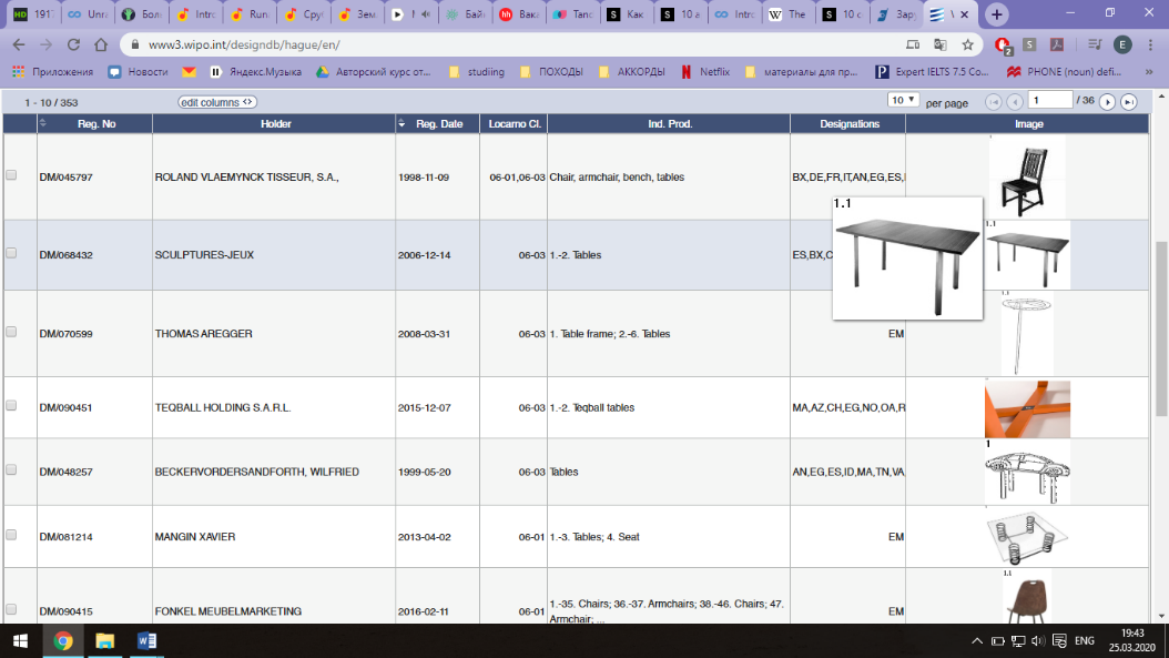 Спускаемся ниже и в строке поиска «Description» вводим ключевое слово поиска на английском (например, «table»), нажимаем «Search» и сайт выдает список патентов попадающие под критерии поиска по ключевому слову;
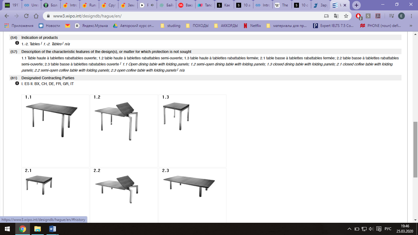
Выбираем патент, близкий к теме дипломного проекта;
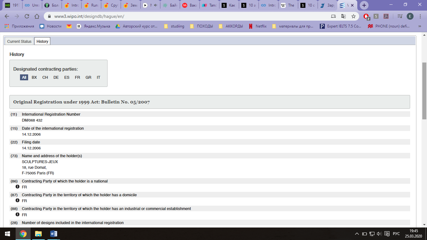 Ниже приведен пример найденного патента:
4. Сайт www.worldwide.espacenet.com
Заходим на сайт www.fips.ru и спускаемся в самый низ, ищем кнопку «Ссылки»;
На открывшейся странице ищем кнопку «Зарубежные БД» (БД – базы данных), нажимаем;
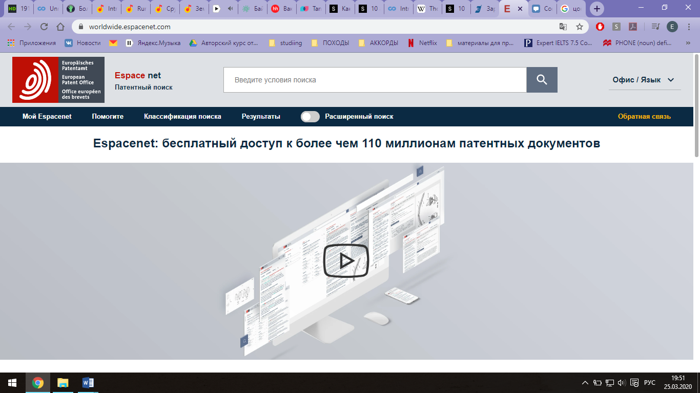
Спускаемся ниже, где изображены Логотипы сайтов для поиска зарубежных патентов, ищем в разделе «БД ведущих патентных ведомств мира» ссылку «Espacenet» (Европейское патентное ведомство), нажимаем;
Спускаемся ниже и нажимаем на ссылку «Classic Espacenet»;
В строке поиска «Smart search» по английски вводим ключевое слово (например, «Design»), нажимаем «Search»;
Из списка выбираем то, что ближе всего к теме;
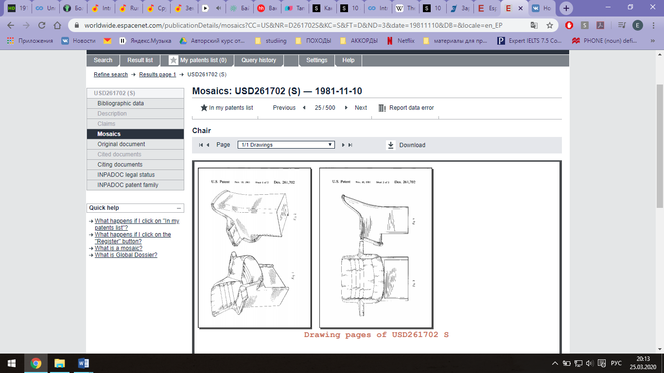
Открылась страница с изобретением, слева есть меню, где есть кнопки «Description» (чтобы увидеть весь текст изобретения), иногда текст изобретения не на английском, но можно перевести на русский или другой язык, сохраняем;
Далее кнопка «Mosaics» (чтобы увидеть чертежи, если они есть), сохраняем;
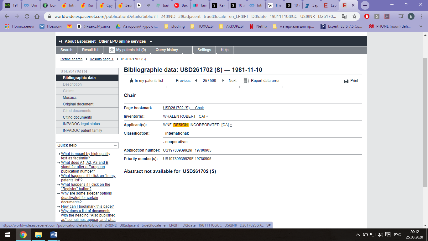 Пример найденного изобретения:
Сайт patft.uspto.gov
Заходим на сайт www.fips.ru и спускаемся в самый низ, ищем кнопку «Ссылки»;
На открывшейся странице ищем ссылку «Зарубежные БД» (БД – базы данных), нажимаем;

Спускаемся ниже, где изображены Логотипы сайтов для поиска зарубежных патентов, ищем в разделе «БД ведущих патентных ведомств мира» ссылку «патенты США с 1790 г., заявки США с 2001 г.» кнопку «патентной БД», нажимаем;
Открывается новая страница с сайтом www.patft.uspto.gov;
Справа ищем ссылку «Quick search», нажимаем;
В открывшейся странице, в строке поиска «Term 1» пишем ключевое слово на английском языке (например, «table»), нажимаем справа «Search»;
Выбираем нужный патент.
Чтобы посмотреть картинки – «Images», чертежи – «Drawings», весь документ – «Full document».
Пример найденного патента:
Можем гулять по вкладкам слева и смотреть отдельные части патента в формате PDF
Полный текст из описания патента:
1-20. (canceled)
21. An apparatus of a user equipment (UE) operable to encode a physical uplink control channel (PUCCH) for transmission to a New Radio (NR) base station, the apparatus comprising: one or more processors configured to: identify, at the UE, uplink control information; identify, at the UE, a demodulation reference signal (DMRS); multiplex, using frequency division multiplexing (FDM) at the UE, the uplink control information and the DMRS onto a plurality of subcarriers in one or more physical resource blocks (PRBs) of one or more orthogonal frequency division multiplexing (OFDM) symbols; and encode, at the UE, the uplink control information that is multiplexed with the DMRS for transmission on the PUCCH to the NR base station; and a memory interface configured to retrieve from a memory the uplink control information and the DMRS.
22. The apparatus of claim 21, further comprising a transceiver configured to transmit the uplink control information that is multiplexed with the DMRS to the NR base station over the PUCCH.
23. The apparatus of claim 21, wherein the DMRS is transmitted on four subcarriers per PRB.
24. The apparatus of claim 21, wherein the uplink control information transmitted over the PUCCH applies an orthogonal cover code over PUCCH symbols and the subcarriers within each OFDM symbol carry different modulation symbols.
25. The apparatus of claim 24, wherein a length of the orthogonal cover code is based on a PUCCH length.
26. The apparatus of claim 21, wherein one DMRS symbol is configured at a middle when a PUCCH length is four symbols.
27. The apparatus of claim 21, wherein the uplink control information transmitted over the PUCCH changes frequency during transmission and one DMRS symbol is configured in one transmission of the PUCCH with five symbols, and two DMRS symbols are configured in another transmission of the PUCCH with seven symbols, when a PUCCH length is 12 OFDM symbols.
28. At least one machine readable non-transitory storage medium having instructions embodied thereon for encoding a New Radio (NR) short duration physical uplink control channel (PUCCH) for transmission from a user equipment (UE) to a Next Generation NodeB (gNB), the instructions when executed by one or more processors at the UE perform the following: identifying, at the UE, uplink control information (UCI) for the UE; multiplexing, using frequency division multiplexing (FDM) at the UE, the UCI and a pseudo-random sequence associated with a demodulation reference signal (DMRS) onto a plurality of subcarriers in one or more physical resource blocks (PRBs) of one or more orthogonal frequency division multiplexing (OFDM) symbols; and encoding, at the UE, the UCI and the pseudo-random sequence associated with the DMRS for transmission on the NR short duration PUCCH to the gNB.
29. The at least one non-transitory machine readable storage medium of claim 28, wherein the one or more PRBs used to form the NR short duration PUCCH include: two or more contiguous PRBs; or two or more non-contiguous PRBs.
30. The at least one non-transitory machine readable storage medium of claim 28, wherein a given PRB used to form the NR short duration PUCCH includes 12 subcarriers, wherein 4 subcarriers of the 12 subcarriers correspond to the pseudo-random sequence associated with the DMRS carried in the NR short duration PUCCH, and 8 subcarriers of the 12 subcarriers correspond to the UCI carried in the NR short duration PUCCH.
31. The at least one non-transitory machine readable storage medium of claim 30, wherein the 4 subcarriers of the 12 subcarriers that correspond to the pseudo-random sequence associated with the DMRS carried in the NR short duration PUCCH include subcarriers 1, 4, 7 and 11 of the NR short duration PUCCH.
32. The at least one non-transitory machine readable storage medium of claim 28, wherein the NR short duration PUCCH that carries the UCI and the pseudo-random sequence associated with the DMRS comprises one or two OFDM symbols.
33. The at least one non-transitory machine readable storage medium of claim 28, wherein the UCI carried in the NR short duration PUCCH includes one or more of: channel state information (CSI), hybrid automatic repeat request acknowledgements (HARQ-ACKs), scheduling request (SR), or beam information.
34. The at least one non-transitory machine readable storage medium of claim 28, wherein the UCI and the pseudo-random sequence associated with the DMRS carried in the NR short duration PUCCH employ length-12 constant amplitude zero autocorrelation (CAZAC) sequences, respectively, when the UCI and the pseudo-random sequence associated with the DMRS are multiplexed using alternating subcarriers in two PRBs.
35. The at least one non-transitory machine readable storage medium of claim 28, wherein the pseudo-random sequence associated with the DMRS carried in the NR short duration PUCCH employs a length-4 discrete Fourier transform (DFT) sequence for each PRB.
36. At least one non-transitory machine readable storage medium having instructions embodied thereon for encoding a New Radio (NR) long duration physical uplink control channel (PUCCH) for transmission from a user equipment (UE) to a Next Generation NodeB (gNB), the instructions when executed by one or more processors at the UE perform the following: identifying, at the UE, uplink control information (UCI) for the UE; multiplexing, using time division multiplexing (TDM) at the UE, UCI symbols associated with the UCI and pseudo-random sequence symbols associated with a demodulation reference signal (DMRS), wherein a number of pseudo-random sequence symbols that are multiplexed with the UCI symbols depends on a length of the NR long duration PUCCH; and encoding, at the UE, the UCI symbols and the pseudo-random sequence symbols associated with the DMRS for transmission to the gNB on the NR long duration PUCCH.
37. The at least non-transitory one machine readable storage medium of claim 36, wherein: the NR long duration PUCCH carries 2 pseudo-random sequence symbols associated with the DMRS when the length of the NR long duration PUCCH is 4 Discrete Fourier Transform-spread-OFDM (DFT-s-OFDM) symbols; or the NR long duration PUCCH carries 3 pseudo-random sequence symbols associated with the DMRS when the length of the NR long duration PUCCH is 7 DFT-s-OFDM symbols.
38. The at least non-transitory one machine readable storage medium of claim 36, wherein the NR long duration PUCCH carrying the UCI symbols and the pseudo-random sequence symbols associated with the DMRS is multiplexed to a PUCCH carrying a scheduling request (SR) sequence of a same length within a same physical resource block (PRB) using different cyclic shifts of a same constant amplitude zero autocorrelation (CAZAC) sequence.
39. The at least one non-transitory machine readable storage medium of claim 36, wherein the NR long duration PUCCH applies a unique orthogonal cover code (OCC) and a unique cyclic shift to the UCI symbols and the pseudo-random sequence symbols associated with the DMRS, respectively, as compared to other UEs when UE multiplexing is employed to multiplex NR long duration PUCCH transmissions for multiple UEs.
40. The at least one non-transitory machine readable storage medium of claim 36, wherein the NR long duration PUCCH that carries the UCI symbols and the pseudo-random sequence symbols associated with the DMRS ranges from 4 Discrete Fourier Transform-spread-OFDM (DFT-s-OFDM) symbols in length to 14 DFT-s-OFDM symbols in length.
41. The at least one non-transitory machine readable storage medium of claim 36, wherein the UCI symbols carried in the NR long duration PUCCH includes one or more of: channel state information (CSI), hybrid automatic repeat request acknowledgements (HARQ-ACKs), scheduling request (SR), or beam information.
Description
BACKGROUND
[0001] Wireless systems typically include multiple User Equipment (UE) devices communicatively coupled to one or more Base Stations (BS). The one or more BSs may be Long Term Evolved (LTE) evolved NodeBs (eNB) or New Radio (NR) next generation NodeBs (gNB) that can be communicatively coupled to one or more UEs by a Third-Generation Partnership Project (3GPP) network.
[0002] Next generation wireless communication systems are expected to be a unified network/system that is targeted to meet vastly different and sometimes conflicting performance dimensions and services. New Radio Access Technology (RAT) is expected to support a broad range of use cases including Enhanced Mobile Broadband (eMBB), Massive Machine Type Communication (mMTC), Mission Critical Machine Type Communication (uMTC), and similar service types operating in frequency ranges up to 100 GHz.
BRIEF DESCRIPTION OF THE DRAWINGS
[0003] Features and advantages of the disclosure will be apparent from the detailed description which follows, taken in conjunction with the accompanying drawings, which together illustrate, by way of example, features of the disclosure; and, wherein:
[0004] FIG. 1 illustrates a New Radio (NR) uplink control channel in accordance with an example;
[0005] FIG. 2 illustrates a short physical uplink control channel (PUCCH) that carries one or two hybrid automatic repeat request acknowledgement (HARQ-ACK) bits in accordance with an example;
[0006] FIG. 3 illustrates a short physical uplink control channel (PUCCH) that carries a one-bit scheduling request (SR) in accordance with an example;
[0007] FIG. 4 illustrates multiplexing of short physical uplink control channels (PUCCHs) for hybrid automatic repeat request acknowledgement (HARQ-ACK) and scheduling request (SR) from different user equipment (UEs) in accordance with an example;
[0008] FIG. 5 illustrates a physical resource block (PRB) and subcarrier configuration for a short physical uplink control channel (PUCCH) that carries more than two uplink control information (UCI) bits in accordance with an example;
[0009] FIGS. 6A and 6B illustrate performances of short physical uplink control channel (PUCCH) structures in accordance with an example;
[0010] FIG. 7 is a table of long physical uplink control channel (PUCCH) formats in accordance with an example;
[0011] FIG. 8 illustrates a long physical uplink control channel (PUCCH) that carries one or two hybrid automatic repeat request acknowledgement (HARQ-ACK) bits in accordance with an example;
[0012] FIGS. 9A, 9B and 9C illustrate a demodulation reference signal (DMRS) structure for a long physical uplink control channel (PUCCH) that carries one or two hybrid automatic repeat request acknowledgement (HARQ-ACK) bits in accordance with an example;
[0013] FIGS. 10A, 10B and 10C illustrate a long physical uplink control channel (PUCCH) that carries a one-bit scheduling request (SR) in accordance with an example;
[0014] FIG. 11 illustrates a long physical uplink control channel (PUCCH) that carries up to a few tens of bits of uplink control information (UCI) in accordance with an example;
[0015] FIGS. 12A, 12B and 12C illustrate a demodulation reference signal (DMRS) structure for a long physical uplink control channel (PUCCH) that carries up to a few tens of bits of uplink control information (UCI) in accordance with an example;
[0016] FIG. 13 depicts functionality of a user equipment (UE) operable to encode a New Radio (NR) short duration physical uplink control channel (PUCCH) for transmission to a Next Generation NodeB (gNB) in accordance with an example;
[0017] FIG. 14 depicts functionality of a user equipment (UE) operable to encode a New Radio (NR) long duration physical uplink control channel (PUCCH) for transmission to a Next Generation NodeB (gNB) in accordance with an example;
[0018] FIG. 15 depicts a flowchart of a machine readable storage medium having instructions embodied thereon for encoding a New Radio (NR) physical uplink control channel (PUCCH) for transmission from a user equipment (UE) to a Next Generation NodeB (gNB) in accordance with an example;
[0019] FIG. 16 illustrates an architecture of a wireless network in accordance with an example;
[0020] FIG. 17 illustrates a diagram of a wireless device (e.g., UE) in accordance with an example;
[0021] FIG. 18 illustrates interfaces of baseband circuitry in accordance with an example; and
[0022] FIG. 19 illustrates a diagram of a wireless device (e.g., UE) in accordance with an example.
[0023] Reference will now be made to the exemplary embodiments illustrated, and specific language will be used herein to describe the same. It will nevertheless be understood that no limitation of the scope of the technology is thereby intended.
DETAILED DESCRIPTION
[0024] Before the present technology is disclosed and described, it is to be understood that this technology is not limited to the particular structures, process actions, or materials disclosed herein, but is extended to equivalents thereof as would be recognized by those ordinarily skilled in the relevant arts. It should also be understood that terminology employed herein is used for the purpose of describing particular examples only and is not intended to be limiting. The same reference numerals in different drawings represent the same element. Numbers provided in flow charts and processes are provided for clarity in illustrating actions and operations and do not necessarily indicate a particular order or sequence.
DEFINITIONS
[0025] As used herein, the term "User Equipment (UE)" refers to a computing device capable of wireless digital communication such as a smart phone, a tablet computing device, a laptop computer, a multimedia device such as an iPod Touch.RTM., or other type computing device that provides text or voice communication. The term "User Equipment (UE)" may also be referred to as a "mobile device," "wireless device," of "wireless mobile device."
[0026] As used herein, the term "Base Station (BS)" includes "Base Transceiver Stations (BTS)," "NodeBs," "evolved NodeBs (eNodeB or eNB)," and/or "next generation NodeBs (gNodeB or gNB)," and refers to a device or configured node of a mobile phone network that communicates wirelessly with UEs.
[0027] As used herein, the term "cellular telephone network," "4G cellular," "Long Term Evolved (LTE)," "5G cellular" and/or "New Radio (NR)" refers to wireless broadband technology developed by the Third Generation Partnership Project (3GPP).
EXAMPLE EMBODIMENTS
[0028] An initial overview of technology embodiments is provided below and then specific technology embodiments are described in further detail later. This initial summary is intended to aid readers in understanding the technology more quickly but is not intended to identify key features or essential features of the technology nor is it intended to limit the scope of the claimed subject matter.
[0029] Mobile communication has evolved significantly from early voice systems to today's highly sophisticated integrated communication platform. The next generation wireless communication system, Fifth Generation (5G), or New Radio (NR) access technology can provide access to information and the sharing of data by various users and applications. NR is expected to be a unified network/system that is targeted to meet vastly different and sometimes conflicting performance dimensions and services. Such diverse multi-dimensional specifications are driven by different services and applications. In general, NR will evolve based on 3GPP LTE-Advanced with additional potential new Radio Access Technologies (RATs) to provide improved, simple and seamless wireless connectivity solutions. NR can enable increased wireless connectivity and deliver fast, rich content and services.
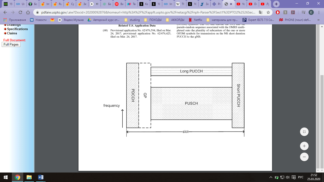
[0030] FIG. 1 illustrates an example of a New Radio (NR) uplink control channel. The NR uplink control channel can include a long duration physical uplink control channel (PUCCH) and a short duration PUCCH within a slot. The long and short duration PUCCHs can be used by a user equipment (UE) to carry uplink control information (UCI) to NR gNBs. Multiple OFDM symbols can be allocated for the long PUCCH to improve link budget and uplink coverage for the control channel. For the long PUCCH, the OFDM symbols can employ Discrete Fourier Transform-spread-OFDM (DFT-s-OFDM), in which DFT precoding is applied before inverse DFT (IDFT) at a transmitter. The long PUCCH can range from 4 DFT-s-OFDM symbols in length to 14 DFT-s-OFDM symbols in length. The long PUCCH can be multiplexed with an UL data channel, such as the physical uplink shared channel (PUSCH), in frequency division multiplexing (FDM) manner. The short PUCCH can be multiplexed with the PUSCH in a time division multiplexing (TDM) manner, and the short PUCCH can employ one or two OFDM symbols. In order to accommodate the DL to UL and UL to DL switching time and round-trip propagation delay, a guard period (GP) can be inserted between the NR physical downlink control channel (NR PDCCH) and the PUSCH.
[0031] In one example, there can be various use cases for the short and long PUCCHs. For example, the short PUCCH can be applicable for UEs close to the gNB, such that the short duration transmission does not incur a serious coverage issue. The short PUCCH can provide higher resource efficiency as it takes a less amount of resources. The short PUCCH can be used for a low latency (delay) transmission due to the short duration, e.g., within a slot, DL data reception and the corresponding UL response on the short PUCCH can be supported. As another example, the long PUCCH can provide a coverage extension for UEs at the cell edge. The long transmission duration can increase the total received signal energy and offset the significant path loss due to the long distance from the gNB. The long PUCCH can provide increased immunity to intercell interference due to additional DFT-s-OFDM symbols within the transmission duration as compared to the short duration PUCCH.
[0032] In one configuration, various designs for the NR short PUCCH are described. Each short PUCCH can carry a different type or payload size of UCI. The NR PUCCHs are designed so that the same time/frequency resource can be shared between different types of PUCCHs and also different UEs in order to enhance efficiency of resource usage.
[0033] In one example, with respect to a short PUCCH to carry 1-2 hybrid automatic repeat request acknowledgement (HARQ-ACK) bits, two contiguous physical resource blocks (PRBs) can be a minimum resource unit. A demodulation reference signal
[0034] (DMRS) and UCI can employ length-12 constant amplitude zero autocorrelation (CAZAC) sequences, respectively, and can be multiplexed in frequency division multiplexing (FDM) on different subcarriers alternatingly. In addition, multiplexing with short SR PUCCH can be supported on either DMRS or UCI subcarriers.
[0035] In one example, pseudo-random sequences are employed for the DMRS and are mapped onto subcarriers. Therefore, when references are made to UCI being multiplexed with the DMRS and mapped onto subcarriers, the UCI is actually multiplexed to a pseudo-random sequence associated with the DMRS, which are then mapped onto the subcarriers.
[0036] In another example, with respect to a different design for a short PUCCH to carry 1-2 HARQ-ACK bits, two contiguous PRBs can be the minimum resource unit for the short PUCCH. A length-12 CAZAC sequence can be applied on even or odd subcarriers within the two PRBs, and on-off keying (OOK) can be employed. In addition, multiplexing with a short HARQ-ACK PUCCH can be supported on either the DMRS or UCI subcarriers.
[0037] In one example, with respect to a simultaneous transmission of HARQ-ACK and SR from a same UE, in cases that a UE transmits HARQ-ACK and SR in the same slot, the comb with SR can be used to deliver HARQ-ACK modulation symbols in order to indicate that active SR has been transmitted from the UE along with HARQ-ACK, and the other comb is used to transmit DMRS for the HARQ-ACK.
[0038] In one example, the set of subcarriers with either even or odd indexes can be referred to as even or odd comb, respectively. When the same signal waveform is repeated within a given duration, then a Discrete Fourier Transform of the signal waveform (which equals a representation of the signal in the frequency domain) results that the signal is mapped on either even or odd comb. Whether the signal is mapped on even or odd combs is determined by whether the same signal waveform is repeated or a sign converted waveform replica is repeated in the 2nd half duration.
[0039] In one example, with respect to a short PUCCH to carry a few tens of UCI bits, the DMRS can be sent on four subcarriers per PRB (i.e., 4 subcarriers per 12 subcarriers), which can result in an overhead of 1/3. Each UCI subcarrier can carry a quadrature phase shift keying (QPSK) symbol corresponding to different UCI encoded bits. In addition, both non-contiguous and contiguous allocations can be supported by the network configuration.
[0040] In one example, in cellular networks, UEs can support various types and payload sizes of UCI. Multiple short PUCCH structures can be employed for carrying 1-2 bits of hybrid ARQ acknowledgement (HARQ-ACK), a 1-bit scheduling request (SR), and a few tens of UCI bits. In designing the short PUCCH structures, sharing time/frequency resource between different types of PUCCHs and also between different UEs can be taken into account in order to enhance resource utilization and spectral efficiency. In addition, the short PUCCH structures can consider flexible configuration of resource amount and locations for the PUCCHs depending on the UCI payload size, deployment scenarios, etc.
[0041] FIG. 2 illustrates an example of a short PUCCH that carries one or two HARQ-ACK bits. The short PUCCH can span two PRBs, which can correspond to 24 subcarriers. The short PUCCH can carry UCI that is multiplexed with a DMRS using FDM, in which the UCI and the DMRS can be in alternating subcarriers. The short PUCCH can employ binary phase shift keying (BPSK) and/or quadrature phase shift keying, as well as CAZAC sequences. For example, the UCI can be a BPSK/QPSK modulated length-12 CAZAC sequence, and the DMRS can be a length-12 CAZAC sequence.
[0042] In one example, as shown in FIG. 2, a short duration PUCCH structure can be employed to carry 1-2 HARQ-ACK bits, which can indicate a decoding success/failure to a received DL data. The transmitted waveform can be based on cyclic prefix OFDM (CP-OFDM) which can multiplex the HARQ-ACK and DMRS signals on different subcarriers. The DMRS and HARQ-ACK can be multiplexed in FDM using different subcarriers alternatingly within two contiguous PRBs. This design can result in a 1/2 DMRS overhead, which can provide an improved performance for a short PUCCH that carries 1-2 UCI bits.
[0043] In one example, two length-12 CAZAC sequences can be applied on the HARQ-ACK and DMRS subcarriers without discrete Fourier transform (DFT) precoding. In this example, BPSK and QPSK modulations can be applied for the cases of 1 and 2 HARQ-ACK bits, respectively. The CAZAC sequence for the HARQ-ACK can be modulated by BPSK or QPSK modulation symbols corresponding to the encoded HARQ-ACK bits, and then mapped on the 12 subcarriers. The DMRS CAZAC sequence can directly be mapped on the subcarriers without modulation. As both sequences are low peak-to-average power ratio (PAPR)/cubic metric (CM) CAZAC sequences, assigning different cyclic shifts to the HARQ-ACK and DMRS sequences can lead to lower PAPR/CM as compared to using the same cyclic shift for both sequences by avoiding constructive combining of waveforms resulting from the HARQ-ACK and DMRS sequences.
[0044] In one example, in view of multiple user multiplexing, the short HARQ-ACK PUCCHs for different UEs can be multiplexed within the same PRB by assigning different cyclic shifts for the CAZAC sequences to the UEs. The cyclic shifts of the HARQ-ACK and DMRS sequences can have a non-zero constant offset for low PAPR/CM, and a UE specific cyclic shift value for each UE can be applied to both the HARQ-ACK and DMRS sequences on top of the constant offset. In addition, multiple sets of two PRBs for the short HARQ-ACK PUCCH can be configured on distant frequency blocks in order to benefit from frequency and interference diversity. By utilizing the DMRS transmitted on each frequency block, the HARQ-ACK PUCCHs sent on the distant frequency blocks can coherently be combined at the gNB receiver. Spatial diversity can be additionally pursued by assigning different cyclic shifts to the PUCCHs transmitted from the respective transmit antennas from a UE.
[0045] FIG. 3 illustrates an example of a short PUCCH that carries a one-bit SR. In this example, a length-12 CAZAC sequence can be applied on even or odd subcarriers within two PRBs with employing on-off keying (OOK). A UE can transmit the sequence on a configured comb when the UE is to have a resource scheduled for a PUSCH transmission in UL, and the SR resource can be left unused otherwise.
[0046] In one example, SR PUCCHs for different UEs can be multiplexed within the same PRB by assigning different cyclic shifts for the CAZAC sequences to the different UEs. Also, as a short SR PUCCH can use either odd or even subcarriers only, the short SR PUCCH can be multiplexed on the corresponding comb with either DRMS or HARQ-ACK of short HARQ-ACK PUCCHs within the same PRB. The cyclic shift offset, comb index and PRB index can be configured via high layer signaling in a UE specific manner. Multiple sets of two PRBs for the short SR PUCCH can be configured on distant frequency blocks as well in order to enhance frequency diversity gain.
[0047] FIG. 4 illustrates an example of multiplexing of short PUCCHs for HARQ-ACK and SR from different UEs. In this example, each UE can be assigned different cyclic shifts for the CAZAC sequences with the minimum cyclic shift offset 3. Each of the SR PUCCHs can be sent on either odd or even comb only with being multiplexed with DMRS or HARQ-ACK sequences of the HARQ-ACK PUCCHs. In cases that a UE happens to transmit HARQ-ACK and SR in the same slot, SR resource can be utilized to deliver HARQ-ACK information in order to indicate that active SR has been transmitted from the UE along with HARQ-ACK. Specifically, the comb with SR for the UE can be used to deliver HARQ-ACK modulation symbols and the other comb can be used to transmit DMRS for the HARQ-ACK.
[0048] For example, in cases that UE 1 and UE 2 are the same UE, a HARQ-ACK modulation symbol can be carried on the CAZAC sequence with cyclic shift 3 on the even subcarriers, which has been assigned for the SR, and the DMRS can be carried on the CAZAC sequence with cyclic shift 9 on the odd subcarriers, which has been assigned for the DMRS. On the other hand, in cases that UE 1 and UE 4 are the same UE, a HARQ-ACK modulation symbol can be carried on the CAZAC sequence with cyclic shift 0 on the odd subcarriers, which has been assigned for the SR, and the DMRS can be carried on the CAZAC sequence with cyclic shift 6 on the even subcarriers, which has actually been assigned for the HARQ-ACK DMRS. The gNB can provide a configuration such that resources for the HARQ-ACK PUCCH and the SR PUCCH for the same UE in a slot are assigned in the same PRBs.
[0049] FIG. 5 illustrates an example of a PRB and subcarrier configuration for a short PUCCH that carries more than two UCI bits. In this example, a given PRB used to form the short PUCCH includes 12 subcarriers, wherein 4 subcarriers of the 12 subcarriers correspond to the DMRS, and 8 subcarriers of the 12 subcarriers correspond to the UCI. In this example, the 4 subcarriers of the 12 subcarriers that correspond to the DMRS include subcarriers 1, 4, 7 and 11 of the short PUCCH.
[0050] In one example, the UCI bits can include CSI, beam information, multiple HARQ-ACK bits and any combination of these UCI types. The DMRS and UCI can be multiplexed in FDM using different subcarriers, and the DMRS can be sent on four subcarriers per PRB, resulting in a DMRS overhead of 1/3, which provides an optimal performance.
[0051] In one example, each UCI subcarrier can carry a QPSK symbol corresponding to different UCI encoded bits. No sequence can be additionally applied on UCI subcarriers, unlike the short PUCCH for carrying 1-2 HARQ-ACK bits, where UCI subcarriers can carry a sequence modulated by a HARQ-ACK BPSK/QPSK symbol.
[0052] In one example for reliable performance of the short PUCCH format, technical aspects such as frequency diversity gain, channel estimation performance and robustness under delay spread can be considered in the structure design. The structure can aim to support up to around 20 UCI bits for a code rate of approximately 1/2. In this regard, three PRBs can be assumed for the short PUCCH format and can carry 24 QPSK symbols with 1/3 DMRS overhead.
[0053] With respect to FIG. 5, various structures can be used for the short PUCCH to carry up to a few dozens of UCI bits. For example, a first structure can employ three contiguous PRBs with a length-12 CAZAC sequence for the DMRS across the PRBs. A second structure can employ three contiguous PRBs with a length-4 DFT sequence for the DMRS on each PRB. A third structure can employ three non-contiguous PRBs with a length-4 DFT sequence for the DMRS on each PRB. Among these three candidate structures, non-contiguous PRB allocations can allow for larger frequency diversity gain and on the other hand, contiguous PRB allocations with a length-12 CAZAC sequence can provide a higher channel estimate SNR and more robustness against inter-cell interference.
[0054] FIGS. 6A and 6B illustrate exemplary performances of short PUCCH structures. These evaluations have been performed for a UCI payload size of 8 bits and a channel root mean square (RMS) delay spread of 100 ns. For non-contiguous allocations, the separation between PRBs is 48 PRBs.
[0055] As shown in FIG. 6A, in case of ideal channel estimation, non-contiguous allocation with a length-4 DMRS sequence can outperform by.about.1.5 decibels (dB) the contiguous allocation cases with length-4 and length-12 sequences. As shown in FIG. 6B, in case of real channel estimation, non-contiguous allocation with a length-4 DMRS sequence can outperform a contiguous allocation with a length-12 CAZAC for a signal-to-noise ratio (SNR) greater than 2 dB and shows similar or worse performance for an SNR less than 2 dB, since the use of a length-12 CAZAC can provide a more reliable channel estimate due to combining the channel estimate for a longer sequence than the cases using length-4 DMRS sequences. Also, in cases that the channel bandwidth is not wide enough to provide sufficient frequency diversity gain for non-contiguous allocations, a contiguous allocation with a length-12 CAZAC sequence can outperform the non-contiguous allocation at an increased level, in relation to FIG. 6B. Therefore, it can be beneficial to enable the gNB to configure the frequency resource for the short PUCCH in non-contiguous blocks or contiguous blocks, taking into account the deployment scenarios, the network bandwidth, channel loading, etc. The configuration can be indicated to each UE via high layer signaling. In case of aperiodic CSI or HARQ-ACK transmissions, a dynamic indication of the resource allocation via downlink control information (DCI) can additionally be applied as well.
[0056] In one example, the described techniques can be extended straightforwardly to cases in which the number of subcarriers, the sequence length and the number of PRBs are different than in the examples described above.
[0057] In one configuration, various designs for NR long PUCCH are described. Each long PUCCH can carry a different type or payload size of UCI, and the number of DMRS symbols within each PUCCH transmission can vary in accordance with the length of the NR PUCCH transmission.