DIY Headtracker
Main RCGroups discussion (recommended reading): https://www.rcgroups.com/forums/showthread.php?t=1677559
Google Code repository: https://code.google.com/p/open-headtracker/
Required hardware
Arduino Nano
9-axis IMU sensor board
Sources for hardware:
Arduino Nano:
Sensor board (9-axis IMU):
Этот проект сделан максимально удобным для пользователя, сохраняя при этом гибкость для разработчиков и мастеров. Необходимо лишь немного технических знаний. Все необходимые настройки могут быть изменены из графического интерфейса пользователя, что облегчает их использование.
Быстрое тестовое видео можно найти здесь. https://dl.dropbox.com/u/3947315/Videogdp.3gp
Схема подключения

Figure: Connection diagram (centering button not shown between D11 and GND)
Assembly and flashing quick guide
You should have:
1 x Arduino Nano or similar
1 x Sensor board
First, let’s assemble the hardware. It's pretty straight forward. Connect the pins as specified in the following table.
| Sensorboard Pin | Arduino Pin |
| Vcc_in | 5 volt |
| GND | Ground/GND |
| SCL | A5 |
| SDA | A4 |
| Transmitter | Arduino Pin |
| PPM_IN | D9 |
| V_out | V_in |
| Ground | Ground/GND |
Optionally, a reset button can be placed between Arduino pin D11 and ground. You can use any momentary pushbutton or toggle switch for this. This button can then be used to re-center the tracker if you change orientation while you’re flying. It can also be used to pause/unpause head tracking by holding the button for 1.5 seconds, if your setup requires this.
The sensor board pins match pretty well with the Arduino pins, so you can just connect it directly. The only pin that doesn't match is ground. I recommend soldering a short wire between one of the Arduino ground pins and the Arduino pin A6 (which is connected to the sensor board’s ground pin). The Arduino pin will be set as an input, so connecting it to ground will not cause any issues with the Arduino’s microprocessor.
The recommended configuration for the sensor board is to place it underneath the Arduino board, like in the following picture. It is, however, possible to remotely mount the sensor board away from the Arduino module, or place it in other configurations. Just make sure the pins match as specified. Please remember that the magnetometer is pretty sensitive. Even small currents nearby will cause a magnetic field. If it's a constant field, chances are you can calibrate it, but please be aware of this problem.
You can test your board without soldering the sensor board and using a temporary jumper between GND and A6. Once your tests are complete and you have the tracker working, solder the sensor board to the Arduino, and solder in a permanent jumper between the Arduino’s GND pin and A6. You can also (optionally) cut or desolder unused pins from the Arduino, including the 6-pin ISP header.
Getting the Arduino software set up:
- Download Arduino IDE from https://arduino.cc/hu/Main/Software (should be version 1 or higher)
- Connect your Arduino board to your PC through the USB connector
- If the driver is installed automatically, just continue. If not, select the folder called "Driver" inside the Arduino IDE folder
- Download the latest headtracker-software from https://code.google.com/p/open-headtracker/
- Open Arduino IDE (the program), Select file -> Open, find the headtracker software downloaded and open the file DIY_headtracker.ino
- You should now have a window looking pretty much like this:

- Go to tools -> Board and select "Arduino Nano w/Atmega328
- Go to tools -> Serial port -> Select the com-port used by Arduino (you should remember the port-number for later use in the GUI).
- Press the left-arrow in Arduino IDE to upload, or select file -> Upload, or press Ctrl + u.
- Hopefully it starts to upload the firmware. It should flash the LED's quickly for
a while, and stop when the upload/programming is complete.
Calibration
Before your headtracker can be used for accurate head tracking, you must first calibrate it. Calibration is done through thecalibration button (or menu option) in the GUI. After you connect the GUI to your headtracker, press the “Calibrate” button and follow the on-screen prompts and pictures.
Hopefully that's it, and you are ready to go.
Некоторые известные ограничения:
• Плата датчика должна быть ориентирована с компонентами вверх.
Графический пользовательский интерфейс

- GUI вид на дополнительные настройки:

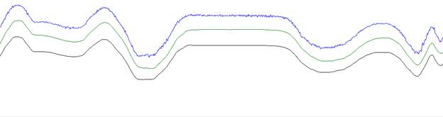
Headtracker сенсорные участки, необработанный, фильтрованный и т.д.:

Using the GUI
PPM channels
Выбор и назначение PPM-канала для pan, tilt, roll.
Center
Центральное положение сервопривода для каждой оси.
End
Конечные точки перемещения сервопривода (максимальные и минимальные)
Gain
Коэффициент усиления определяет, сколько сервопривод должно двигаться для заданного количества движения трекера. Значение по умолчанию - 170, что в значительной степени дает 1: 1 (90 градусов движение головы = 90 градусов сервомеханизм).
Все "advanced settings"
- - - -
LP filter at tilt/roll [%]
Низкочастотный фильтр конечного tilt / roll выхода.
1 = максимальная нижняя граница / постоянная времени. Дает очень плавное, но также очень медленное изменение.
100 = Низкочастотный фильтр выкл.
LP filter at pan [%]
Фильтр нижних частот конечного выхода pan.
1 = максимальная нижняя граница / постоянная времени. Дает очень плавное, но также очень медленное изменение.
100 = Низкочастотный фильтр выкл.
Gyro weight on tilt/roll [%]
Сколько мы нажимаем на гироскоп по сравнению с акселерометром на оси наклона / валка? Акселерометр является шумным и его следует использовать только для медленной компенсации дрейфа.
100 = использовать только гироскоп.
0 = использовать только акселерометр
Gyro weight on pan [%]
Сколько мы используем гироскоп по отношению к акселерометру на оси tilt / roll? Акселерометр является шумным и его следует использовать только для медленной компенсации дрейфа.
100 = использовать только гироскоп.
0 = использовать только акселерометр
Servo pulse variation
Это: регулировка хода сервопривода.
Используется для установки максимального изменения ширины импульса в сигнале PPM. Устройство представляет собой микросекунды * 2 - относительно таймера Atmega
Servo center
Это: нейтральное положение сервопривода
Используется для установки центра / стандартной длины ширины импульса в сигнале PPM. Устройство представляет собой микросекунды * 2 - относительно таймера Atmega
Tilt and roll gain
Усиление сервопривода. Вы решаете, хотите ли вы поворачивать голову на 10 градусов или на 360 градусов, чтобы получить полный ход.
Pan gain
Усиление сервопривода. Вы решаете, хотите ли вы поворачивать голову на 10 градусов или на 360 градусов, чтобы получить полный ход.
Reverse (Tilt, roll and Pan)
используется для инверсии направления сервопривода.