Cooling-heating thermostat consists of:
Control panel.
Thermostat attached to the device block.
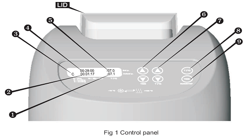
On the control panel of the unit are:
Control keys and LCD display. (see Fig 1)
On the rear panel of the unit are:
Plug-in cable.
Power switch.
Getting Started
Unpacking
Remove packing materials carefully and retain for future shipment or storage of the unit.
3.2 The PCH-1 set includes:
Peltier heater/cooler PCH-1..................................1 piece
12 x 1.5ml + 20 x 0.5ml capacity block................1 piece
External power supply unit..................................1 piece
Mains lead............................................................1 piece
Operating Manual; CE Certificate.........................1 copy
3.3 The PCH-2 set includes:
Peltier heater/cooler PCH-2................................1 piece
20 x 1.5ml capacity block...................................1 piece
External power supply unit.................................1 piece
Mains lead...........................................................1 piece
Operating Manual; CE Certificate........................1 copy
3.4 Plug the external power supply unit into the 12 V socket at the rear side of the PCH-1/2.
Operation
4.1 Connect power supply unit to the mains power.
4.2 Switch ON the power switch located on the rear panel of the PCH-1.
4.3 The backlit display on the PCH-1 shows the following:
Previously set time and temperature.
Operation mode indicator, current time and temperature.
4.4 Temperature setting. Use the T (°C) up/down keys (6) to set the necessary temperature. When the key is pressed down for 1 second or more, the temperature display changes quickly. Temperature increment is 0.1 °C.
Note that it is possible to change the set temperature in the real time, i.e. it is not
necessary to stop heating/cooling process to make these changes.
Connect power supply unit to the mains power.
4.5 To start heating/cooling to the set temperature press T (°C) on the RUN/STOP key (8) once.
4.6 The PCH-1/2 starts heating/cooling and the corresponding operation mode is indicated on the display (H - heating, C - cooling) (3). Current temperature is displayed in the second line of the display (1).
4.7 To stop the heating/cooling process press T (°C) RUN/STOP key once again. It may take a few moments before the process stops and the operation mode indicator shows S - stopped.
4.8 When the necessary temperature is reached, open the PCH-1/2 block lid, place tubes into the sockets and close the lid. Use standard tubes, since the block sockets are made precisely in compliance with their size and shape.
4.9 The PCH-1/2 is equipped with an independent reaction timer. This alerts time-up with an audible alert; it does not control the heating/cooling process.
4.10 Use the TIME up/down keys (6) to set the necessary time, shown in the first line of the display (4). (When the key is pressed down for 1 second or more, the time display changes quickly). Time increment is 1 minute.
|
|
Note that it is possible to change the set time in the real time, i.e. it is not necessary to stop the timer to make these changes.
4.11 Press TIME RUN/STOP key (9) once, to start the timer. When the set time is reached the timer will stop and a buzzer will sound.
ATTENTION!
The timer does not switch off the heating/cooling.
4.12 If necessary, the timer can be stopped before the set time is reached by pressing TIME RUN/STOP key.
4.13 When TIME RUN/STOP key is pressed again, the timer starts counting up the time from zero.
4.14 Once the heating/cooling process has finished, turn OFF the PCH-1/2 with power switch located on the rear panel and disconnect the external power supply unit from t he mains.
Maintenance
Where applicable all Grant laboratory products are designed to comply with IEC61010-1 and can be flash tested. Some are fitted with radio frequency interference suppressers. Therefore it is recommended that only a D.C. test be performed. No other routine service is required.
Cleaning
The cases can be cleaned with a damp cloth after disconnection. Do not use solvents.
Before using any decontamination or cleaning method except that recommended, check with our Service Department, or in other countries with our distributor, that the proposed method will not damage the equipment.
Specifications
Temperature regulation range.......................................................- 10°C to + 100°C
Range of possible temperature from 30 C below Room Temperature to + 100 C
Setting resolution............................................................................................±0.1°C
Working room temperature range.......................................................15°C to +27°C
Independent timer with sound signal.....................................................0 to 96 hours
Time setting unit............................................................................................minutes
Current time display unit................................................................................seconds
Display.......................................................................................................16x2 LCD
Capacity
PCH-1.................................................0,5 ml tubes x 20 psc + 1,5 ml tubes x 12 pcs
PCH-2........................................................................................1.5ml tubes x 20 pcs
Thermoblock cover...................................................................................transparent
External power supply:
input.....................................................................AC 100-240 V, ~ 50-60 Hz, 1.5 A
output.................................................................................................DC 12 V, 5.0 A
|
|
Maximum power consumption..........................................................................60 W
Dimensions.....................................................................................240x260x165 mm
Weight...............................................................................................................3.6 kg
To improve the design manufacturer reserves the right to make changes in specification without prior notice.
Guarantee and Service
Guarantee
When used in laboratory conditions and according to these working instructions, this product is guaranteed for TWO YEARS against faulty materials or workmanship.
Service
For service, return for repair to our Service Department in the UK or, in other countries, to our distributor.
SECTION III
TRANSLATION PRACTICE
Work algorithm
Step 1. Read the text.
Step 2. Define the possible source of the text and its target audience.
Step 3. Define the purpose of the text.
Step 4. Define the thesis statement.
Step 5. Define the main ideas that support the thesis statement.
Step 6. Define the typological features of the text.
Step 7. Define the translation domains conditioned by the typological features of the text.
Step 8. Translate the text.
Text 1
The Test Plan
Engineers at the Seismo-Build research project would not be worried or even surprised next month if their new building collapsed under the force of a powerful simulated earthquake.
They have constructed a 167-square-metre, 36,288-kilo, wood-frame, mid-rise experimental building, which they plan to attach to the top of the massive piston-powered E-Defense shake table in Japan, the largest in the world. Before the shake begins, the building will be fitted with 240 displacement, strain and acceleration sensors and 50 LED light markers to allow optical monitoring via motion-recording video cameras.
Once secured to the shake table, the building will be subjected to a series of three incrementally-increasing seismic simulations, starting with magnitude 6.7, then 7.1 and finally 7.5. between tests, no repairs will be carried out to any damage to the building.
The building is fitted with seismic dampers, each one about 44 centimetres long and 7.6 centimetres thick, attached to the base of triangular steel frames embedded within the walls of the house. Each fluid-filled damper is capable of absorbing kinetic energy, converting it into heat up to 93°C and dissipating up to 6,800 kilos of force, or the equivalent of 20 car shock absorbers.
The engineers expect the dampers to absorb much of the energy from the movement of the house, but they don’t know yet whether this would be enough to protect it from damage, as they hope.
|
|
The team fully accepts that it could suffer significant damage and could even collapse completely. It is, after all, a destructive test. However, even a total collapse would provide useful data.
The project team have a clear purpose in running this three-test experiment. They hope that the tests will yield significant data about how well the seismic dampers cushion the effects of the three simulated earthquakes on the building.
If successful, the experiment could change the way wood-frame buildings are designed and built in earthquake zones. The experiment is part of a long-running engineering project to design economical easy-to-build wood-frame houses that can withstand powerful earthquakes.
Text 2