REPORT
On laboratory work №7
On the discipline “Electrical machinery”
Specialty: 5B071800- Electrical Power Engineering
Done by: Shaimuradov E. Group: EPEe-15-10
Checked by: Abdulaev Z.M.
_________ ___________ “___” __________ 2017
(score) (signature)
Study of a three-phase synchronous motor
Purpose of work: familiarization with the asynchronous start-up of a three-phase synchronous motor (SM) and the study of its operating properties by removing experimental characteristics.
Program of work:
1. to study the scheme for the experimental study of the synchronous motor, the composition and purpose of the modules used in the work.
2. asynchronously start
3. take off the performance of the SM
4. remove the U-shaped characteristics of the SM
5. To carry out the processing of experimental data, compile a report and make a conclusion on the work
Explanations for work:
In the laboratory work the following modules are used:
- stand power supply module (SPSM)
- power supply module (PSM)
- autotransformer module (ATM)
- power module(PM)
- module of additional resistance №2 (MAR №2)
- power measuring module (PMM)
- measuring module (MM)
Before conducting laboratory work, you must bring the modules to their original state:
- switch SA1 of module ATM to the lower position; turn the rotor of the automatic converter to the extreme left position;
- switch CA1 MAR №2 set to "  "
"
The investigated synchronous motor is part of the electric machine assembly, which includes the M1 engine itself, the load generator- the DC machine M2, the pulse speed sensor M3.
Asynchronous start of a synchronous motor
Scheme for asynchronous start of a synchronous motor given in figure 1.

Figure 1
The asynchronous start is carried out in the following sequence:
- turn on the QF1 and QF2 modules SPSM and PSM, accordingly, the synchronous machine will accelerate to the subsynchronous speed;
- Switch SA1 of module ATM to the upper position, changing the position of the autotransformer knob, observe the change of the rotor current IE along the device PA and the synchronization of the SM.
After the LED snaps into sync, you can take off its working characteristics.
Working characteristics of SD
The scheme for working characteristics is shown in Fig. 1
Working characteristics are present the dependencies Ic, P1, M2, η and cosφ= f(P2) at Uc= IE SM= const.
Removal of working characteristicsis carried out in the following sequence:
- set the excitation current of the SM IE SM= 1A, it is necessary to take into account that the voltage after the diode rectifier differs from the input voltage by Kф=1.11.

- by the switchingSA1 of the module MAR №2 to increase the load of the GDC until the SM drops out of synchronism or the current of the GDC armature reaches the nominal value Iload= IN= Ia(Ia= 1.3A).
Record the experience data in Table 1
Table 1

Table 2

After the experiment, install the modules in the initial state, turn off the automats QF1 AND QF2.
U-shaped characteristics of SM
The U-shaped characteristics are the dependences of the current of the starter IS and cosφ on the excitation current IESM at the moment of loading M = const. Iccosφ= f(IESM)
The circuit for removing the U-shaped characteristics of the SM is shown in fig. 2
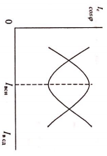
Appearance of U-shaped characteristics of SM
Removal of the U-shaped characteristics of the SM is carried out in the following sequence:
- perform asynchronous start of the SM
- set the excitation current of the SM to be equal to IESM= 0.5A
- set switch SA1 of module MAR №2 to load current Il= 0.5A
- increase the excitation current by turning the autotransformer handle
Record the experience data in Table 3
Table 3

Increase current of load to Il= 1A and repeat experiment.
After the experiment, install the modules in the initial state, turn off the automats QF1 AND QF2.
Listofreferences
1 Копылов И.П. Электрические машины.-М.: Высшая школа, Логос, 2000. -607 с.
2 Брускин Д.Э., Зорохович А.Е., Хвостов В.С. Электрические машины. Ч. 1,2. -М.: Высшая школа, 1987.
3 Копылов И.П. Электрические машины.-М.: Энергоатомиздат, 1986.-360 с.
4 Вольдек А.И. Электрические машины.-Л.: Энергия, 1978.-832 с.
5 Костенко М.П., Пиотровский Л.М. Электрические машины. Ч.2 Машины переменного тока.- Л.: Энергия, 1973. - 412 с.