Concept
1. Title page
2. Task…………………………………………………………….……………………………………………..2
3. Concept…………………………………………………….……………………………………………….4
4. Normative references………………………………………………………………………………………………….5
5. Definitions………………………………………….………………………………………………………6
6. Designations and abbreviations…………………………………...………………………………………………………7
7. Introduction………………………………………………………………………………………………8
8. Main part
- analytical review (study of analogues and sketches of the author). 13
- description of the volume-spatial solution;..................................... 14
- description of the architectural - planning solution.........................15
- description of the constructive solution;..........................................17
- description of the facade solution....................................................18
- description of the general plan……………………………………………………….19
9. Conclusion
In this course project the following definitions are used.
Monofunctional building - a public building with one function
A module is a constant multiple that is taken as the basis of some form for coordinating the dimensions of parts of a building or complex, for example, a model of a public building can be built from cubes. And this model will be proportional and spectacular, because the modular cubes will ensure the harmony of the perception of the composition. Plans for all buildings have their own module.
Combinatorics is a special form of shaping, the essence of which is changing the shape based on various combinations of the same type of elements.
An integrated method - a systematic approach with the simultaneous development of all aspects of design: urban planning, functional planning, constructive, economic and architectural and artistic
Methodology - a way to effectively achieve a goal or a specific task
Technical floor - floor for placement of engineering equipment and laying communications
Analysis is a method of scientific research, based on the decomposition of the whole into its component parts.
Climate – Statically long-term weather in a particular area, characterizing the state of the air atmosphere
Landscape - terrain and vegetation
Geotechnical conditions
- type of soil, the presence of groundwater, the degree of subsidence and other characteristics of the territory
Aeration - organized and controlled natural air exchange of a building or territory
Insolation - illumination with direct sunlight, characterized by duration and measured in hours
INTRODUCTION
Improving the welfare of the population of Kazakhstan causes the design and construction of public buildings. In connection with the development of small and medium-sized businesses, the following public buildings are in greatest demand: exhibition halls, car dealerships, fitness centers, cafes, etc. The construction volumes of modern public buildings can be compact. The spatial planning solution of these buildings depends on the social needs of the population and the wishes of the customer. The customer here may be the city administration or private entrepreneurs. Architects have the main task -
to design an individual project. This project should be modern and differ in architectural and artistic expressiveness. The city administration strives to build public buildings attractive in architectural and artistic terms. This building should be the hallmark of the city, justify the investment, be attractive to citizens and tourists. Therefore, the author of the project must design the building with full responsibility. He must study the allocated area for construction. By many multiple sketches and sketches to design a unique building, create an architectural and artistic ensemble, transform the architectural environment of the construction site.
In the educational process of architectural education, the following complex requirements should be presented that were formulated by the ancient Greek architect Vitruvius in the 2nd century. BC: "Architecture is a benefit, strength, beauty." This definition is not outdated at the present time.
Benefit. Public buildings must first be suitable. For example, school planning should be convenient for schoolchildren, have spacious, lighted classes, laboratories, etc.
Strength. Buildings must be sufficiently resistant to seismic effects, hurricanes, floods, etc. By the definition of scientists, buildings with a round, square, hexagonal, octahedral shape are stable in case of an earthquake. The most seismic-resistant forms of high-rise buildings with a wide base and tapering with increasing number of storeys.
Beauty. Modeled buildings should be beautiful, modern and spectacular.
Manufacturability. Buildings should be convenient for operational construction. Complex, unreasonable configurations of buildings do not attract construction contractors. The proposed below method for constructing a model from small cubes simulates a frame construction and is convenient for educational design.
Landscape, transformation of the environment. Designed buildings should blend in beautifully with the environment and urban situation.
In the city, a building with its shape, silhouette, turn, combination with the surrounding buildings should create a beautiful urban landscape. High-rise buildings can also be presented with 7-8 viewpoints: from the main square, street, pedestrian mall, metro station, etc.
Taking into account the highest specified requirements - I have completed the project of an exhibition hall with an area of 5600 square meters. According to the task of the department for the construction of this object is selected
intersection of Kaziev and Argynbekov streets. The following existing facilities are located here: a zoo, parks, a department store, and mid-rise private developers. The author of the project took into account the existing communications, transport and pedestrian communications and executed this project in the high-tech style. The relevant sections contain the parameters and description of the characteristic parts of the project according to the requirements of the design assignment.
- analytical review (study of analogues and sketches of the author)
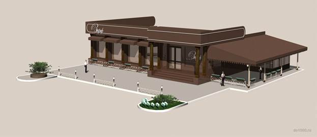
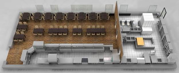
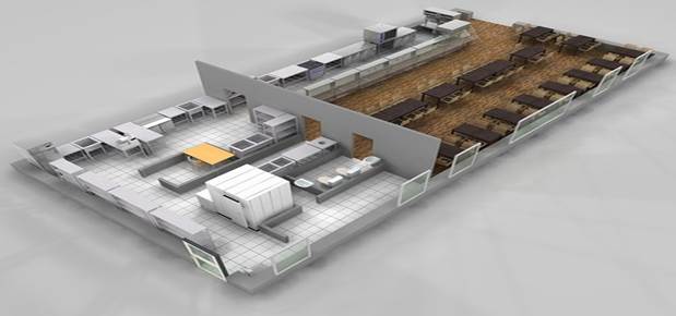
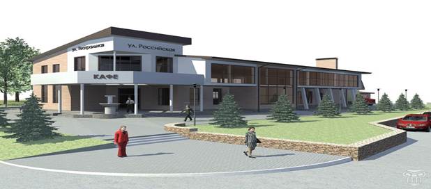
The cafe.The explanatory note consists of 105 pages, including 47 tables, 28 sources, 7 supplements. The graphic part is done on 10 pages of Al size. This graduation work arregement a plan of cafeteria, disposition of production promises and equipment, with water admition, canalization, energy, also technological schemes of cooking, assortment and terms of products quality. Production program of an enterprise has been defined taking into account of the number of customers, dishes, consumption of basic materials and uncooked food. A menu with a free choice is done. Also the technological accounting and election of equipment (mechanical, thermal, chilling, auxiliary), the number of staff of production and in the hall. The effectiveness of the project has been estimated by costs on primary and auxiliary material, equipment, water, energy, salary, amortization and social payments and other costs. The self-cost of the dishes and the retail price have been defined. On the basis of this data the period for cost recovery has been defined.
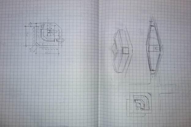
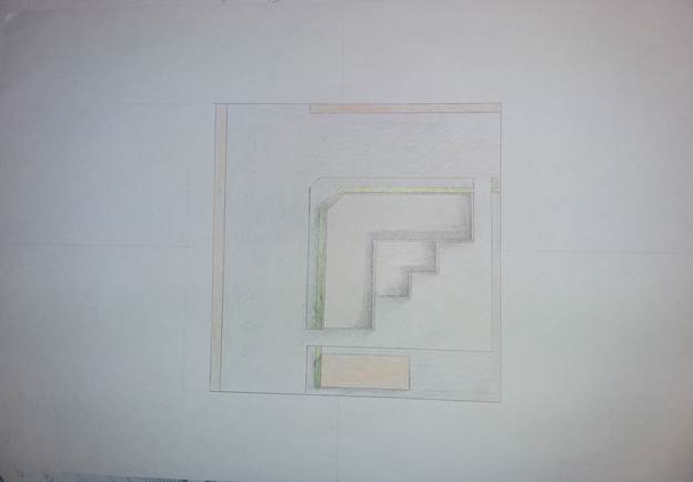
- sketches of author
- 
VOLUME - SPATIAL
PROJECT COMPOSITION
VSP is formed in a three-dimensional volume. An example of this is the composition of modern residential public buildings known all over the world: the Bourges Al –Arab Hotel, the Sydney Opera House, the KIA Tower in Kuwait, etc. The search for a composite solution is carried out by sketching and modeling, while modern shaping should be taken into account buildings. Architects use various artistic images for this: the shape of a sailboat on the seashore, plants growing in a given area, etc.
To stimulate the creative activity of students, you can use the search modeling of architectural objects.
Plasticine - this plastic material is convenient to use for modeling small architectural (sculptural) forms: children's playgrounds, fountains, benches, garden stairs, etc. It allows you to quickly, visually make the main idea, allows you to make small fragments and parts. Skillful use of colored clay allows you to achieve maximum similarity with the designed object.
Polyfoam (coarse-grained, sold in hardware stores) is convenient for modeling and revealing the plastics of public and residential buildings of average height. The height of each layer of foam (5 cm) must correspond to the height of the building. For example, a 5-storey building consists of 5 layers of foam. This type of foam is easy to cut using a stationery cutter. The pieces or layers of foam are easily attached to each other with an ordinary toothpick. When prototyping, specific dust is emitted in the form of small balls, therefore, to clean the audience, it is necessary to stock up in advance with a vacuum cleaner.
Small cubes are made of wood (3 cm x 3 cm) or folded from paper in the form of origami (3 cm x 3 cm). For homework, you can use sugar cubes (1.5 cm x 1.5 cm; 1.5 cm x 0.8 cm). Small cubes model the grid of the frame construction of residential and public buildings measuring 6m x 6m x 3 m (x2).
They are convenient for finding the artistic image of frame buildings. It is not recommended to glue the cubes with each other, since the stability of the shape of the model simulates the stability of the structure of the designed building. This type of material is convenient for both the search for forms of spatial and spatial composition.
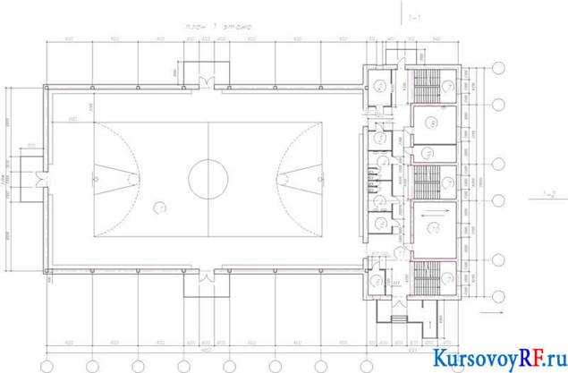
Execution of building plans
The plan of the building is the image of his (building) horizontal section. Depending on the content of the drawing and its purpose, on the location of the section plane, the following plans are carried out: Floors - the main type of floor plans (often referred to as floor plans); foundations, floors, floors, roofs, etc. The floor plan (building) gives an idea about the space-planning composition of a building, about the location of walls, columns and other fencing and supporting structures, their binding to the grid of coordination axes, about the location of all rooms on the floor, about their purpose, size and shape, the location of stairs, windows, doors, sanitary equipment.
When executing floor plans of residential buildings, an imaginary horizontal cutting plane is placed within the door and window openings of each floor and, accordingly, plans of the first, second and subsequent floors are obtained.. The first floor plan is drawn in any case. If the layout of the second and subsequent floors is the same, then they draw a general plan for them and call it “Typical Floor Plan”, or “Plan 2... 4 floors”, etc. The floor plans are given the name indicating the clean floor mark, floor number or designation of the corresponding section plane, for example: “Plan at mark. 0.000 ”,“ Plan 3-3 ”, etc.
The layout of the building plans on the drawing sheet must comply with GOST 21,101-79. As a rule, the long side of the plan is placed along the horizontal (long) side of the sheet.
School building plans are positioned so that the wall of the main facade is parallel to the horizontal side of the sheet. Floor plans are placed on the sheet in ascending order of floor numbering from bottom to top or from left to right.
The order of drawing the floor plan: the layout of the drawing plan; drawing a grid of focal axes; binding and tracing of bearing and enclosing structures on the plan; plotting plan details; drawing sizes and inscriptions; drawing design
When applying the grid of coordination axes, it is necessary to take into account the presence of seams, deformation, temperature, in places of elevation differences, since in most cases such seams are placed on paired axes.
By dimensioning, all supporting structures of the building are linked to the coordination axes, i.e. the elements of the plan are coordinated; after binding, all external and internal walls, partitions, and columns are drawn.
Outside the dimensions of the floor plan, three or four chains of sizes are affixed:
1st, 2nd chains: the binding of the walls and the outer edges of the walls to the coordination axes, the dimensions of the walls and openings
3rd chain: the distance between the extreme coordination axes, the binding of the axes of the extreme columns;
4th chain: the overall dimensions of the building, i.e. distances between extreme coordination axes.
The dimension line of the first dimensional chain is carried out.
at a sufficient distance from the outline of the plan so that there is enough space for drawing explanatory signs and marks and not to impede the reading of the plan. The distance between adjacent dimension lines takes 6... 10 mm.
Inside the floor panel dimensions are put down:
binding of walls to coordination axes, partitions - to coordination axes or to the surface of walls; thickness of walls and partitions; dimensions of the premises (width, length); dimensions of openings in internal walls and fixed partitions.
On the floor plans they apply: marks of the clean floors of the floors, located in different levels; floor slopes, space in the lower right corner of the room, m2, up to two decimal places and underline with a solid thick line
At the drawing design stage, check the drawing, make the necessary changes, remove the extra lines, and produce a final stroke.
The orientation of the building should be latitudinal. The facades of the building are oriented to the south and east. The bearing elements of the building are drawn in thick lines.
In other types of stores, it is allowed to design public toilets at the rate of one sanitary appliance for every 600 m2 of retail space in non-food stores and for every 400 m2 of retail space in food stores, but at least two sanitary appliances.
. Public toilets should have: • at least one cabin with a minimum width of 1.65 m and a depth of at least 1.8 m for wheelchair users;
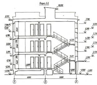
Making sections of the building
The cuts are designed to identify the space-planning (architectural) and constructive solutions of the building.
Drawings of sections of buildings are manufactured in accordance with GST 21.501-80 and the recommendations below.
perform sections of buildings with a vertical cutting plane perpendicular to the longitudinal walls, a cross-section, or parallel to them a longitudinal section. The position of the cutting planes for the construction of the cut begin in the design process
so that when
the minimum number of cuts most fully
Cross sections: a) - architectural, b) - to identify the volumetric and constructive solutions of the building. Heights, etc. and so that the cuts show openings of windows, exterior doors and gates, staircases (the cutting plane must pass along the stairway closest to the observer), elevator shafts, balconies, loggias, etc.
Regardless of the position of the section plane, the longitudinal section of the building within the attic is depicted along the ridge of the covering. The position of the cutting plane is depicted on the plan.
first floor sectional line.
Depending on the purpose of the document, the following cuts are made:
architectural - contain data on the total volume of fig. ten
composite solution. Such cuts are developed in
initial design stage. They contain simplified images of the elements of the ground part of the building without detailing the structures of the walls, covering floors, etc. On cuts
apply only dimensions and elevations.
Constructive - except for the volume-composition solution I, contain images of structures, marking of nodes and structural elements, all necessary dimensions and elevations.
In the drawings of the sections of buildings put all the dimensions and marks necessary to determine the position of any structural element. Outside the overall contours of the section put down:
distances between all focal and extreme axes; marks the bottom of the slabs covering the upper floor of multi-storey buildings; mark the top of the walls, eaves. ledges of walls; dimensions and binding openings, holes. niches and nests in walls and partitions, depicted in sections. In addition, the drawings of the cuts of buildings put down the distance from the top of the opening of the upper floor to the top of the parapet or cornice, mark the top and bottom of the openings, platforms for external stairs, ridge of the roof, etc. They put the dimensions of the height of the premises, the thickness of the floors, including the floor, marks the bottom of the floor
Graphic design of the section is the final stroke of the contours of the visible elements, removing auxiliary elements.
 The sections of the building are given a common sequential numbering in Arabic numerals within the main set of drawings.
Execution of facades
Images of the exterior of the building - the facades give an idea of the architectural composition of the designed object, its silhouette. The drawings of the facades are included in the general architectural and construction solutions of the project.
The drawings of the facades are carried out in accordance with GOST 21.501-80, and the recommendations given below.
On the drawing of the facade should be applied and indicated:
general view of the building and details. Characteristic coordination axes are extreme; The dimensions between the coordination axes are not set down; elevations - the level of the ground, the entrance step, the top of the walls, the bottom and the top of the openings, the bottom of the loggia and balcony plates, the canopies above the entrances, the eaves of the ridge of the roof ridge.
The plans and cuts determine the dimensions of the dimensional rectangle of the facade. In the accepted scale of the drawing, a dimensional rectangle is drawn so as to evenly use the sheet area, to place the text part, the main title, the name of the facade, coordination axes, elevations.
Building a facade grid
on the lower horizontal side of the dimensional rectangular mark the position of the characteristic coordination axes, window and door openings and walls. Vertical lines are drawn through the received currents. On the vertical side of the dimensional rectangle, the height and height of marks taken from the section of the building are marked with the bottom and top of the window and door openings, the bottom of the balcony and loggia plates, basement, parapet, etc. and draw horizontal lines
drawing the main contours.
On the resulting grid depict the overall contours of the facade. window and door openings, loggias and other elements.
drawing details.
Apply window covers, doors, fencing loggias and balconies, etc.
Drawing elevations, b brands of coordination axes, elements of external walls, protections of balconies, loggias, etc.
The metric system of measures has been used in architecture worldwide since the beginning of the twentieth century. The module of the metric system is 1m - 100cm, for example, the outer size of low-rise buildings is determined in integer meters 10m x12m, 12m x 12m, 14m x 18m, etc.
The small module of the metric system is 0.3m -30cm. A small module is used to determine the height of a building equal to 3 mile, 3.3 m, - 3.6 m, 4.2 m. This module is also used to determine the size of window and door openings. For example, the size of the external door opening can be 90 cm x 210 cm, and window apertures - 150 cm x 120 cm, 150 cm x 150 cm, 150 cm x 180 cm, 150 cm x 210 cm, etc.
A large module 6 m is used for high-rise buildings, the size of a multi-story frame building is, for example,
12 m x 36 m (42 m, 48 m, 60 m) or 18 m x 18 m (24 m, 30 m), etc.
The height of the floor of these buildings can also be determined by a small modulus of 0.3 m, corresponding to 3 m, 3.3 m, 3.6 m, 4.2 m, etc.
Ergonomics
Human factors and ergonomics (commonly referred to as human factors) is the application of psychological and physiological principles to the (engineering and) design of products, processes, and systems. The goal of human factors is to reduce human error, increase productivity, and enhance safety and comfort with a specific focus on the interaction between the human and the thing of interest.
The field is a combination of numerous disciplines, such as psychology, sociology, engineering, biomechanics, industrial design, physiology, anthropometry, interaction design, visual design, user experience, and user interface design. In research, human factors employs the scientific method to study human behavior so that the resultant data may be applied to the four primary goals. In essence, it is the study of designing equipment, devices and processes that fit the human body and its cognitive abilities. The two terms "human factors" and "ergonomics" are essentially synonymous.
The International Ergonomics Association defines ergonomics or human factors as follows:
Ergonomics (or human factors) is the scientific discipline concerned with the understanding of interactions among humans and other elements of a system, and the profession that applies theory, principles, data and methods to design to optimize human well-being and overall system performance.
Human factors is employed to fulfill the goals of occupational health and safety and productivity. It is relevant in the design of such things as safe furniture and easy-to-use interfaces to machines and equipment.
Proper ergonomic design is necessary to prevent repetitive strain injuries and other musculoskeletal disorders, which can develop over time and can lead to long-term disability.
Human factors and ergonomics is concerned with the "fit" between the user, equipment, and environment. It accounts for the user's capabilities and limitations in seeking to ensure that tasks, functions, information, and the environment suit that user.
To assess the fit between a person and the used technology, human factors specialists or ergonomists consider the job (activity) being done and the demands on the user; the equipment used (its size, shape, and how appropriate it is for the task), and the information used (how it is presented, accessed, and changed). Ergonomics draws on many disciplines in its study of humans and their environments, including anthropometry, biomechanics, mechanical engineering, industrial engineering, industrial design, information design, kinesiology, physiology, cognitive psychology, industrial and organizational psychology, and space psychology
Physical ergonomics
Physical ergonomics: the science of designing user interaction with equipment and workplaces to fit the user.
Physical ergonomics is concerned with human anatomy, and some of the anthropometric, physiological and bio mechanical characteristics as they relate to physical activity. Physical ergonomic principles have been widely used in the design of both consumer and industrial products. Physical ergonomics is important in the medical field, particularly to those diagnosed with physiological ailments or disorders such as arthritis (both chronic and temporary) or carpal tunnel syndrome. Pressure that is insignificant or imperceptible to those unaffected by these disorders may be very painful, or render a device unusable, for those who are. Many ergonomically designed products are also used or recommended to treat or prevent such disorders, and to treat pressure-related chronic pain.
One of the most prevalent types of work-related injuries is musculoskeletal disorder. Work-related musculoskeletal disorders (WRMDs) result in persistent pain, loss of functional capacity and work disability, but their initial diagnosis is difficult because they are mainly based on complaints of pain and other symptoms.]Every year, 1.8 million U.S. workers experience WRMDs and nearly 600,000 of the injuries are serious enough to cause workers to miss work. Certain jobs or work conditions cause a higher rate of worker complaints of undue strain, localized fatigue, discomfort, or pain that does not go away after overnight rest. These types of jobs are often those involving activities such as repetitive and forceful exertions; frequent, heavy, or overhead lifts; awkward work positions; or use of vibrating equipment. The Occupational Safety and Health Administration (OSHA) has found substantial evidence that ergonomics programs can cut workers' compensation costs, increase productivity and decrease employee turnover. Therefore, it is important to gather data to identify jobs or work conditions that are most problematic, using sources such as injury and illness logs, medical records, and job analyses
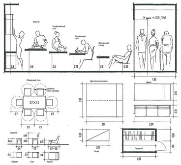
Anthropometric conditionality of the size of the elements of the medium filling.