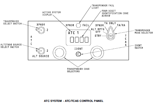
The transponder mode selector has several positions. These are the functions that the ATC system uses:
- TEST - This push button on the top of the mode selector starts an ATC transponder functional test.
- STBY (standby) - A ground discrete goes to both transponders. This ground discrete prevents operation of the transponder, but does not prevent built-in-test-equipment
(BITE) functions.
- ALT RPTG OFF (altitude reporting off) - The active transponder responds to ATC interrogations. The reply does not contain an altitude report.
- XPNDR (transponder) - The active transponder responds to ATC interrogations. Mode C and Mode S altitude replies contain altitude information.
You use the function select switch to select one of these TCAS modes:
- TA ONLY mode. This is the TA only mode. The display of RAs is prevented.
- TA/RA mode. The displays show all targets. This is the normal mode of operation for TCAS.
IDENT Switch.
When the ATC controller requests the airplane identifier, the flight crew pushes the momentary IDENT switch. The transponder adds a special position identification (SPI) pulse to the interrogation reply for the next 18 seconds.
Altitude Source Switch.
Use the two-position switch to set the source of altitude data for the ATC transponder.
When you set the switch to the number 1 position, ADIRU 1 supplies the altitude data. When you set the switch to the number 2 position, ADIRU 2 supplies the altitude
data.
The XPNDR FAIL light comes on for these conditions:
- Transponder failure
- Antenna failure
- Control data failure.
- Altitude input failure.
When you set the switch to the number 1The ATC/TCAS control panel controls the TCAS computer
The ATC/TCAS control panel controls the TCAS computer.
TEST SWITCH
You can use the test button in the center of the switch to do a test of the ATC and TCAS systems.
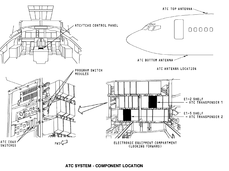
ATC SYSTEM - COMPONENT LOCATION
Flight Compartment
The ATC/TCAS control panel is on the P8 aft electronics panel.
Electronic Equipment Compartment
These are the ATC transponder system components in the electronic equipment compartment:
ATC transponder 1
ATC transponder 2
Program switch module (2)
Top ATC coax switch
Bottom ATC coax switch.
ATC Antenna Location
The ATC antennas are on the forward fuselage near the centerline. The top ATC antenna is at STA 430.25. The bottom ATC antenna is at STA 355.
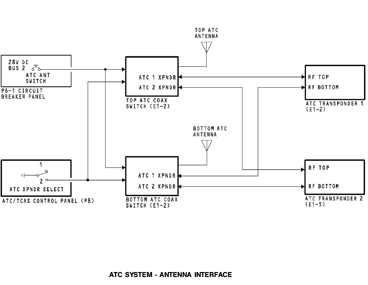
ATC SYSTEM - ANTENNA INTERFACE
General
The ATC coax switches get power through the ATC ANT SWITCH circuit breaker. When you select ATC transponder 1 on the ATC/TCAS control panel, the ATC coax switches do not energize and the antennas connect to ATC transponder 1. When you select ATC transponder 2, the ATC/TCAS control panel sends a discrete ground to the ATC coax switches. This energizes the coax switches and connects the top and bottom antennas to ATC transponder 2.
ATC SYSTEM - POWER, IDENTITY, CONTROL, AND AIR DATA INTERFACES
Power