Air Traffic Control (ATC) needs to identify all aircraft flying in the local airspace quickly and accurately. ATC controllers need to accurately locate and identify all aircraft flying in their sector. ATC controllers have two types of radar systems to help them in their task, PRIMARY and SECONDARY. The principles of primaiy radar have already been discussed so the following is meant as revision.
Primary Radar
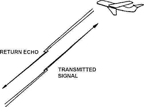
A high power transmitter sends out a radio signal and waits to see if it is reflected off any object in the signal's path. Analysis of these reflections helps the radar operator to determine the location, velocity and heading of a target (aircraft).
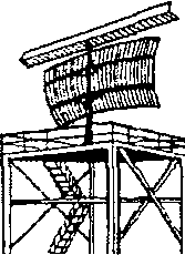
The transmitted signal is a series of short pulses of energy. These pulses are accurately spaced apart to allow detection of any reflected signals or echoes from a target. As the speed of radio waves is known the target's range is calculated from the time difference between the start of the transmitted pulse and the start of the returned echo pulse. To increase the accuracy of Primary Radar, the radio signals are concentrated into a narrow beam that transmits from a rotating aerial called a Scanner.
|
The controller's two-dimensional display is synchronised with the scanner's rotation, and echoes are represented on it as a spot of light, commonly called a radar 'Blip'. This blip shows the range and bearing of the aircraft from the ground radar transmitter, figure 13.
 RADAR SCANNER
|
RADAR PRINCIPLES
This system works well, but controllers cannot readily identify one aircraft from another when there are several flying close together, eg when in a holding stack. It also cannot separate aircraft flying in the same location but at different altitudes. Consequently, to overcome these problems, Secondary Surveillance Radar (SSR) systems were developed.
Secondary Surveillance Radar
The aircraft is fitted with a transponder that transmits a signal back to the ground radar each time it is struck by the ground radar interrogation signal.
An aircraft's Transponder system now forms an integral part of the ATC Radar network and aircraft cannot fly in controlled airspace without one within the UK. Indeed, in most countries a Transponder is now mandatory for all aircraft flying in controlled airspace.
The aircraft's Transponder sends a four-digit identifying code signal, and if selected, a readout of the aircraft's altitude, in response to an interrogation from a ground based SSR. ATC controllers use the response from all replying Transponders to help locate and identify aircraft flying within range of the Radar and so maintain proper separation between them.
Transponders operate in the Lband of the frequencies, around 1,000 MHz. The ground SSR system usually uses an antenna mounted directly on the primary radar scanner, synchronised with the same rotation pattern. It transmits its interrogations on 1030 MHz and the aircraft's Transponder replies on a different frequency, 60 MHz above it, of 1090 MHz.
Aircraft Equipment
An aircraft's Transponder system has the following components:
* Transmitter / Receiver
* Controller
* 'L' Band Omni-Directional Antenna
* Altitude Input Data
Most modern aircraft have dual Transponder systems fitted, but can only use one at a time. Figure 14 shows a block diagram of how these components are interconnected in a typical aircraft installation.
Transmitter / Receiver
The transmitter and receiver are usually housed within in one LRU. This contains all the electronics required to receive signals and transmit replies. It also contains circuits to monitor its own integrity and for checking the validity of the interrogating signal.
The receiver portion has the electronics required to receive and decode the ground Radar's interrogating signal of 1030 MHz.
The transmitter portion has the necessary circuitry to generate and transmit a carrier wave signal at 1090 MHz, superimposed or modulated by a series of pulses that make up the unique return code.
Transponder Controller
As only one Transponder system can be transmitting at any one time, an aircraft usually has only one shared controller in a dual installation. A switch, usually located on the controller, switches operation from one system to another. Figure 15 shows a typical example.
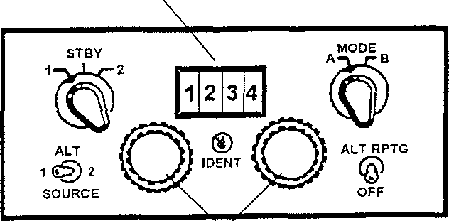
Code Selection dials
Fig. 15 TYPICAL TRANSPONDER CONTROLLER
Operation of the Controller
STBY 1/2 Used to select which Transponder is in use when the aircraft has dual systems fitted.
ALT 1/2 Used to select the source of altitude information.
MODE Selects mode of reply signal, although Mode B is not widely used at present.
ALT RPTG When selected, it switches on automatic transmission of the aircraft's altitude, ie Mode C.
IDENT When pressed, it will intensify the radar blip on the ground TC display for about 20 seconds.
CODE DISPLAY A four-digit display that shows a readout of the selected code, from 0000 to 7777.
CODE DIALS Allows selection of each digit in the display between '0' and 7'.
L Band Antenna
The aircraft antenna for each Transponder system is an 'L' band, Omni-directional type, mounted on the bottom of the aircraft. (L-band means it operates most efficiently at approximately 1,000 MHz). Aircraft designers must ensure it fits in an area not masked or shielded from the ground signals. This helps to prevent the Transponder from losing the ground station signal and consequent loss of the aircraft's identification on the ATC display. The antenna may be blade shaped to reduce aerodynamic drag.
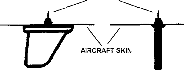
DIRECTION OF FLIGHT
Fig. 16 TRANSPONDER ANTENNAS
Altitude Input
The altitude source for the Transponder can come from one of two sources, an Encoding Altimeter or a Central Air Data Computer (CADC).
Most light aircraft, below 2,700kg, and older aircraft built before the mid 1970s, use an encoding altimeter. This type of altimeter works like (and to a pilot looks the same as) a conventional static driven altimeter but pick-off circuits within the instrument convert the pressure height into a digital signal. This signal is directly proportional to the aircraft's altitude (see the Instrument section of this module). Most altimeters of this type feed the digital signal directly to the Transponder controller. As a cheap alternative, a 'blind' altimeter, ie one with no visual display, is sometimes fitted on a convenient bulkhead behind the instrument panel.
Modern aircraft have replaced the conventional altimeter and other air data driven instruments with servo driven indicators. These are driven electrically by a Central Air Data Computer (CADC), which receives Pitot static data, processes it and converts it into a digital format. It then sends it direct to the Transponder transmitter/receiver.
SSR Ground Station
As already described, the SSR Transponder antenna is mounted directly above the primary radar scanner and moves in synchronisation with it. As with primary radar, the SSR interrogation is also formed into a narrow beam. The replies from both the primary radar and the aircraft Transponder are added together on one display, with the aircraft's unique code and altitude information displayed next to the echo blip, figure 17.
The SSR interrogates all aircraft, about their identity and current flying altitude. It does this by transmitting a signal on 1030 MHz, modulated with a set of pulses, with the spacing between pulses deciding the mode of interrogation.
In civil aviation, Mode A interrogations are used to request the aircraft's identity and Mode C interrogations request the aircraft's altitude. Modes B and D are available but are not currently in use.
As shown in figure 17, the Mode A interrogation pulses, PI and P3 are 8 µS apart, and each pulse is 0.8 µS wide. This pulse width is the same for all four modes. The Mode C pulses, PI and P3, are 21 µS apart. The ground SSR splits its transmissions between the Mode A and C interrogations, not necessarily on a 50- 50 basis, as usually the SSR transmits two Mode A interrogations for every one Mode C.
As you can see in figure 18, there are three pulses in each interrogation. Pulses 1 and P3 are transmitted from the rotating SSR antenna, while pulse P2 radiates from a separate, Omni-directional antenna. This pulse is always transmitted 2 µS S after the PI pulse, in all modes. It is used as a reference signal for the aircraft's Transponder to recognise false interrogations from the SSR's side lobes, figure 19.
Pulse P2 amplitude is set at the same level as the maximum side lob (figure 20). If the aircraft Transponder receives pulses PI and P2 at or near the same level, (within 10 dB), it will ignore the interrogation.
Obviously, only those aircraft equipped with a Transponder reply to the SSR's interrogations. However, SSR replies are displayed on the controller's radar screen, called a Planned Position Indicator (PPI), with all the primary radar returns.
The images presented on the PPI remain until the next sweep of the screen so the controller does not have to remember the position of each aircraft. Modern electronics and new display techniques mean that aircraft returns on the controller's PPI can be categorised by aircraft type. For example, aircraft without a Transponder could be displayed as a circle, SSR replies as a single or double dash and military aircraft as a star. It also means local topographical features and airways information can be superimposed on the screen to give the controller a complete picture of his/her operating sector (figure 21).
Local airways information superimposed on PPI
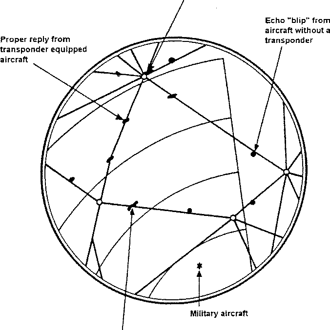 Aicraft transponder transmitting "(dent" pulse
Fig. 21 TYPICAL PPI DISPLAY
Aicraft transponder transmitting "(dent" pulse
Fig. 21 TYPICAL PPI DISPLAY
|
PPI symbols will vary depending on the radar installation. In controlled airspace, where all aircraft must have a Transponder, individual aircraft are displayed as a small square with three trailing dots that show its previous position and direction of travel.
Typical Operation
Most Transponder operations are automatic once the pilot selects the identification code given by ATC. A typical operation sequence is given below:
1. Pilot selects the identification code given by the ATC and switches the Transponder on.
2. The ground SSR transmits its interrogation pulses on 1030 MHz as the primary radar detects the aircraft.
3. The aircraft's Transponder receives the interrogation signal, checks for side lobes, and decodes the pulses.
4. The aircraft's Transponder formulates the reply signal, depending
on the interrogation mode and type of response required, encodes and transmits a reply on 1090 MHz.
5. ATC ground station decodes the reply from the aircraft, combines it with the primary return signal and displays it on the PPI.
How Does a Transponder Work?
As already discussed, the aircraft Transponder receives the SSR interrogation pulses on 1030 MHz. The received signal feeds through a duplexer, a device that switches the system's antenna to the transmitter or receiver circuits at the proper time, to filter and amplification stages. Once filtered and amplified, the 1030 MHz signal is mixed with a fixed injection signal, locally generated within the receiver, to reduce its frequency to a more manageable level. This signal is further amplified and applied to a detector stage. The detector stage incorporates a side lobe suppression (sis) system that checks the validity of the pulses by looking at the amplitude of pulses PI and P2 (figure 22).
If the detector sees correct levels of PI and P2 it goes on to check the spacing between PI and P3. It does not interpret the spacing, but merely confirms they are 8 µS, 17 µS, 21 µS or 25 µS apart, ie a valid interrogation Mode. The detector feeds valid interrogations to the pulse decoder, but if it detects invalid interrogations, it disables the pulse decoder and the Transponder does not reply.
The pulse decoder measures the time difference between pulses PI and P3 to determine the interrogation mode. Once this is known, the decoder applies a trigger signal to a mode selector and an encoder. The mode selector chooses what group of reply pulses are returned to the SSR; aircraft ident if a Mode A interrogation, the aircraft's altitude if a Mode C interrogation. The encoder formats the reply pulses into the correct sequence according to the aircraft's identification or altitude, as appropriate.
An aircraft's flight crew select the identification code on the instructions of the ATC controller. This four-digit code ranges from 0000 to 7777. jr0r a Mode A reply, the encoder selects which pulses to send from a maximum of twelve pulses, figure 23.
Figure 23 shows the maximum number of pulses that would be transmitted and represents the aircraft identification code 7777. Pulses Al, A2 and A4 make up the first digit, pulses Bl, B2 and B4 the second digit, and so on. Each pulse can only have two states, on or off, in computer terms a logic 1 or a logic 0, and make up each digit as in Table 3.
| Number | Pulse 1 | Pulse 2 | Pulse 4 |
| TABLE 3 MODE A REPLY PULSE ALLOCATION |
Pilots should take care when selecting codes, as certain combinations are used for emergency situations only. Any code beginning with 77, ie 77XX, causes the aircraft's symbol on the ATC display to appear brighter and wider, and also initiates an audio warning to the ATC controller. This tells the controller the aircraft has an emergency, but not what the emergency is. Code 7600 is used to show when an aircraft has suffered a total radio failure.
To help ATC controllers deal with today's crowded skies, light aircraft flying in uncontrolled airspace, not under the direct control of ATC, are encouraged to set their Transponder Code to 4321. This is not mandatory yet, but does provide valuable help to controllers, especially where there is a high concentration of light aircraft, eg around the peripheral areas of large cities eg London.
As already discussed the SSR requests altitude information on every third interrogation. If the aircraft is not equipped with an altitude reporting system, or it is switched off, the Transponder simply ignores this interrogation. However altitude reporting is available using a format known as the Gilham Code. This code uses the pulses to show 100 foot increments in altitude. To allow reporting of altitudes of less than zero feet, the Gilham code starts at minus 1,000 feet, as shown in table 4.
| Altitude | C4 | C2 | CI | B4 | B2 | B1 | A4 | A2 | A1 | D4 |
| -1000 | ||||||||||
| 1,000 | ||||||||||
| 10,000 | ||||||||||
| 50,000 |
| TABLE 4 SAMPLE MODE C REPLY PULSES |
In un-pressurised aircraft that seldom fly above 10,000 feet, Transponders may not use the 'D' pulses at all when reporting the aircraft's altitude. This helps keep down the production costs for the Transponder and encoding altitude.
The aircraft's Transponder can also provide a special identification pulse when requested by ATC. However, it is only initiated by the flight crew pressing the 'IDENT' button on the controller. The ident pulse is tagged onto the end of a Mode A or C reply and is transmitted for 18 ± 2 seconds (figure 24).
It causes the aircraft's symbol on the ATC display to expand, so it can easily be distinguished from other returns, ATC controllers usually ask an aircraft to 'squawk ident' when they first come under their control, to aid initial identification.
After sorting out the reply pulses, the encoder sends them to the modulator for adding to the carrier signal. This is then multiplied up to the reply frequency of 1090 MHz and fed to the duplexer. The duplexer switches the antenna from receive to transmit mode and the reply signal is transmitted back to the SSR.
When the Transponder is transmitting, it also generates a suppresser pulse that is applied to other L band equipment in the aircraft, eg DME. This protects the receivers of other L band equipment by temporarily disabling their receiver circuits while the Transponder is transmitting.
The Transponder also has circuits that provide self-monitoring to check for the aircraft system's reliability and to guard against over interrogation. A Transponder will respond to a maximum of 2,000 interrogations per second, but as most ground stations only transmit at 400 interrogations per second, this usually does not cause a problem. It is only in congested flying areas, such as London- Heathrow and the east coast of the USA, where this happens, when the Transponder reduces its sensitivity to only respond to the strongest 2,000 interrogations.
Transponder Range
A Transponder's operating range depends on several factors, eg the aircraft's altitude, terrain between SSR and aircraft, SSR transmitting power, etc. The aircraft Transponders' power output will depend on the aircraft type and installation. Light aircraft have Transponders with a power output of 125 watts giving 100 nm range at 10,000 feet. While large aircraft Transponders may have a power output over 1,000 watts and have a range of 200 nm at 30,000 feet. In either case the Transponder relies on line-of-sight operations, and any obstacles between the SSR and aircraft, eg mountains, will affect the system's maximum range.
Troubleshooting
As the aircraft's Transponder's operation is mostly automatic, and the flight crew have no indications of the system's workings, it is usually the ATC controller that reports any problems. Typical areas of interest to an engineer will include:
* What exactly did the ATC controller report?
* Do both systems have power?
* Does the problem occur on both systems?
* Has any other ground station reported problems with receiving signals from this aircraft.
* Does the problem occur with Mode A and Mode C replies?
* Does the problem only occur with a particular code selected?
* Some transponder controllers have a 'reply light' to show when the system is transmitting. If one is fitted, does it operate properly?
MODE S TRANSPONDER
The Mode S Transponder is a new system that enhances the operation of SSR systems by adding a data-link capability; an ability to selectively interrogate aircraft; and other performance improvements. With a Mode S system, the existing Mode A/C Transponder transmitter/receiver is replaced by a Mode S transmitter/receiver. However, Mode S Transponders still work with standard SSR ground stations that can only interrogate in Mode A and C Modes with no deterioration of performance.
When used with a suitable ATC ground station, the aircraft's Mode S Transponder will only respond when addressed, not eveiy time the ATC radar beam sweeps past. From the aircraft's Mode S replies, the ATC Controller can identify each aircraft by its tail identification or flight number automatically.
Mode S response codes are assigned to each aircraft at the time of the Transponder installation and are not on the control head. The identification code, ie aircraft tail identification, is set by the system installer using installation jumpers on 24 pins on the Transponder mating connector. Each discrete aircraft address is obtained from the appropriate regulatory authority, ie FAA on US registered aircraft, CAA on British, prior to installation.
As discussed above, the Mode S Transponder also responds to conventional Mode A and Mode C interrogations; the type of response depends on how it is interrogated. Mode A interrogation, the response code is that set on the control head, and the operation from the flight crew standpoint is the same as a conventional Transponder. A Mode C interrogation would obviously initiate a Mode C, ie altitude reporting.
This new system provides ATC with improved surveillance accuracy with minimised interference. It can distinguish between two aircraft at the same azimuth but different altitudes by asking them to respond one at a time. It reduces interference as the Transponder only replies when requested, not at the same time, which results in clutter on the controller's PPI.
Mode S Transponder also provides data link capability for ground-to-air, air-to- ground and air-to-air, which is a requirement TCAS II/III collision avoidance, ie the co-ordination of manoeuvre intentions between aircraft, which is described in more detail below.
The air-to-ground and ground-to-air features are to request and receive flight advisory and ATC services currently under development and essential for Future Air Navigation Systems (FANS).
Mode S Operation
The Mode S system operates in a similar fashion to a standard Mode A system. As a Transponder equipped aircraft enters the airspace, it receives the ATC Mode S 'all call» interrogations, which can be identified by both standard arid Mode S Transponders. Mode A Transponders reply as described above, but the Mode S Transponder replies with a Mode S format that includes a discrete 24~bit Mode S address.
The Mode S SSR uses monopulse processing to determine the azimuth bearing of an aircraft from a single reply, instead of a series of replies as required by standard systems. The ground monopulse antenna generates two separate patterns; a single or sum pattern and a dual lobe difference pattern. The two patterns simultaneously receive each Transponder reply. The ratio of the energy received by the sum pattern to the energy received by the difference pattern determines the bearing of the aircraft from the antenna bore-line. Once detected, the address and the position of the Mode S aircraft is entered into a roll-call file. On the next scan, the Mode S aircraft is discretely addressed and these discrete interrogations contain a second field that may desensitise the Mode S Transponder to further Mode S 'all-call' interrogations. This is called Mode S lockout.
Standard Mode A and C interrogations from SSR are not affected by this lockout. Mode S Transponders reply to the interrogations of a Mode A and C interrogator under all circumstances.
All Mode S ground stations are, or soon will be, digitally linked, and as a Mode S aircraft flies into the airspace served by another Mode S SSR, the first Mode S SSR may send position information and the aircraft's discrete address to the second interrogator via ground lines. This eliminates the need to remove the lockout and the second SSR may schedule discrete roll-call interrogations for the new aircraft coming into its sector. Because of this discrete addressing feature, Mode S SSRs can work at a lower rate or handle more aircraft. Each Mode S interrogation contains a 24 bit discrete address that allows a very large number of aircraft to operate in an air traffic control environment without the occurrence of a redundant address.
A Mode S aircraft reports in its replies, either its altitude or its Mode A 4096 code depending on the type of discrete interrogation received. However, during each scan, aircraft interrogations are made in both Mode A and Mode C for non Mode S equipped aircraft, it is just that the Mode S equipped aircraft only responds to specific interrogations.
When a SSR does not receive a valid reply as it scans through a Mode S aircraft's location, the SSR can re-interrogate a limited number of times. Normally, SSRs interrogate at low power, known as «whisper»and re-interrogate at high power, known as (shout if the low power interrogation fails. Figure 25 shows the interrogation pattern from a Mode S SSR.
For this drawing the SLS pulses have been ignored as their function has already been described above. The Mode S Transponder receives an interrogation from the ground and will initiate a normal Mode A or C reply until the presence of the P4 pulse is detected. Once the P4 pulse is detected the reply is terminated. If the width of the P4 pulse is 0.8 µS then no reply is transmitted.
However, if the width of the pulse is 1.6 µS, a Mode S reply is generated 128 µS after the leading edge of the P4 pulse. The Mode S reply is the same reply generated in response to the Mode S all-call interrogation. The standard replies are described below.
The Mode S Transponder is capable of improving air-to-air surveillance and communications when equipped with two antennas. Such systems are called Diversity Systems. One antenna is mounted on the top of the aircraft and the other on the bottom.
The Diversity Mode S Transponder system has automatic selection of the appropriate antenna, based on the relative strength of detected interrogation signals if the signals are received simultaneously. If the detected interrogation signals are not received simultaneously, ie within 0.125 the Transponder selects the interrogation signal that arrived the earliest. The selected antenna is used to receive the remainder of the interrogation, and if required, transmit the Mode S, A or C reply.
Mode S Message Content
The Mode S message content is extensive and is outside the scope of these notes but the following paragraphs are intended to give a basic introduction to them.
In addition to normal interrogations, the Mode S Transponder is capable of air-air communication with other Mode S equipped aircraft and is also capable of:
ELMs are Extended Length Messages and can be received and transmitted to the ground. However, the structure and content of these are outside the scope of these notes.
The primary function of Mode S is surveillance and to accomplish this function the Mode S Transponder uses the 56 bit transmissions in each direction. In the 56 bit transmissions, the aircraft reports its altitude or Mode A 4096 code and its flight status, ie airborne, on ground etc.
The discrete addressing and digital encoding of Mode S transmissions, however, allow their use as a digital data link as the interrogation and reply formats of the Mode S system contain sufficient coding space to permit the transmission of data. These data transmissions may be used for ATC purposes, air-to-air data interchange for collision avoidance, or to provide flight advisory services such as weather reports, or Automated Terminal Information System (ATIS) data.
Most Mode S data link transmissions will be handled as one 56 bit message included as part of a long 112 bit interrogation or reply. These transmissions include the message in addition to the surveillance data. These longer messages are transmitted using the extended length message (ELM) capability. The ELM is capable of transmitting up to sixteen 80-bit message segments, either ground-to- air or air-to-ground.
ATC В737.
General
The air traffic control (ATC) ground stations interrogate the airborne ATC system. The ATC transponder replies to the interrogations in the form of coded information that the ground station uses.
The ATC transponder also replies to mode S interrogations from the traffic alert and collision avoidance systems (TCAS) of other airplanes or ground stations.
When a ground station or a TCAS computer from another airplane interrogates the ATC system, the transponder transmits a pulse-coded reply signal. The reply signal identifies and shows the altitude of the airplane.
Maximum airspeed
TCAS coordinating signals
TCAS status
Altitude
Mode A identity code
Twenty-four bit address.