General
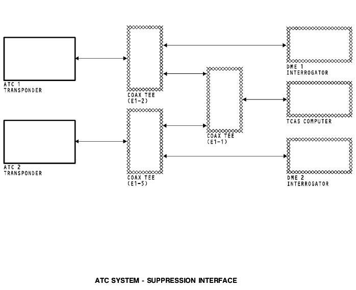
The ATC transponders, TCAS, and the DME interrogators operate in the same frequency band. There is a suppression interface between these units. This prevents damage to the receiver circuits during a signal transmission. The suppression circuits also prevent responses from onboard equipment. The first unit to transmit sends a suppression pulse to a coax tee. The coax tee divides the suppression pulse and sends it to the different units, or to a different coax tee. This suppression pulse prevents the operation of the receiver circuits in the other units.
ATC SYSTEM - ATC TRANSPONDER
General
The ATC ground station interrogates the ATC transponder with a pulse-coded signal at a frequency of 1030 MHz.
The transponder responds with pulse-coded signals at a frequency of 1090 MHz.
Characteristics
The transponder responds to air traffic control radar beacon system (ATCRBS) mode A and mode C interrogations. The transponder also responds to air traffic control and the TCAS computer with the mode select (mode S) format.
The ATC transponder has a non-volatile flight-fault memory.
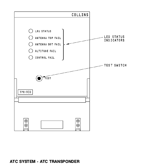
Front Panel Indications
The test switch starts a self-test.
The light emitting diode (LED) status indicators on the front panel show for these conditions:
LRU STATUS (green), if there are no LRU failures
LRU STATUS (red), if there is an LRU failure
ANTENNA TOP FAIL, if the top antenna fails
ANTENNA BOT FAIL, if the bottom antenna fails
ALTITUDE FAIL, if the altitude input from the ADIRU fails
CONTROL FAIL, if the control panel input fails.
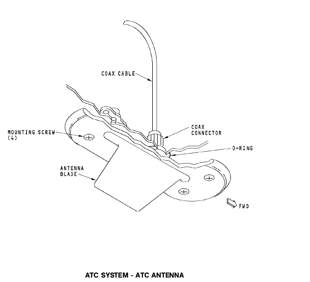
ATC SYSTEM - ATC ANTENNA
Purpose
The ATC L-band blade antenna receives 1030 MHZ interrogation signals from ATC ground stations and other airplanes that have TCAS. The ATC transponder transmits the reply signals through the L-band antenna.
Physical Description
The coaxial cable connector connects to the antenna. The antenna has an O-ring moisture seal and attaches to the airplane by four screws. The ATC and DME antennas are the same and are interchangeable.
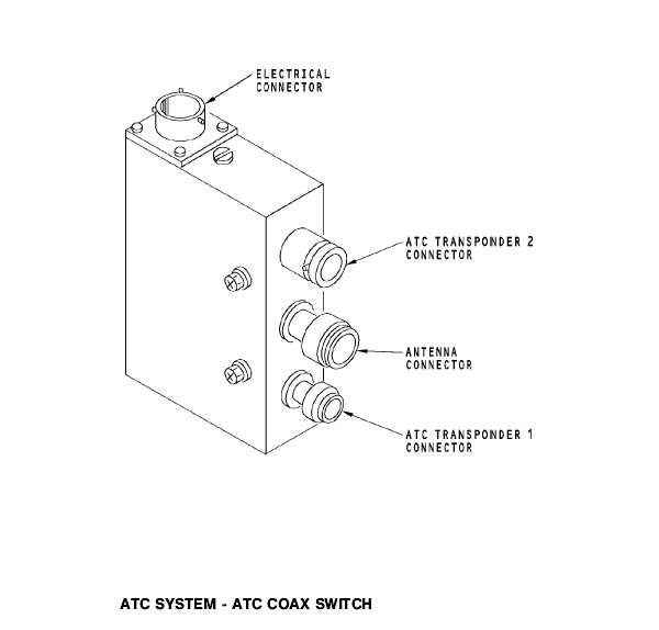
ATC SYSTEM - ATC COAX SWITCH
General
The ATC coax switches connect the active ATC transponder to the top and bottom ATC antennas.
These are the electrical connector inputs:
ATC antenna switch circuit breaker
ATC/TCAS control panel.
The ATC coax switches supply an RF interface for the ATC system interrogation and reply signals. These are the connectors:
ATC transponder 1 connector
ATC antenna connector
ATC transponder 2 connector.
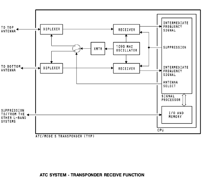
ATC SYSTEM - TRANSPONDER RECEIVE FUNCTION
General
The antennas send the interrogation signals to the transponder.
The signals go through the diplexer circuits to two receivers. The 1030 MHz interrogation signal mixes with a 1090 MHz signal from the 1090 MHz oscillator. This makes an intermediate frequency signal that the signal processor uses.
Suppression
When the transponder gets a suppression pulse from another system, the signal processor circuits do not permit the receiver circuits to operate.
Antenna Select
The antenna select circuit chooses the diplexer and antenna that supplies the strongest receiver signal. The transmission of the reply signal goes through the selected diplexer and antenna.
Signal Processor
The signal processor determines if the transponder receives a valid interrogation signal. It also determines the correct reply mode; mode A, mode C, or mode S.