Transmit
The central processor unit (CPU) controls the transponder to reply to a mode A, mode C, or mode S interrogation. The mode format circuits use the identity code, airplane altitude and the unique 24-bit airplane address from the memory to format the data for the reply signals.
The mode A reply contains the airplane identity code.
The mode C reply contains the airplane altitude.
The mode S replies contain a unique 24-bit airplane address, identity code, altitude information, and TCAS information. After the signal processor chooses the correct mode for the reply data, the modulator makes a reply signal in that format. The modulator uses the signal processor output to modulate a 1090 MHz carrier to make the transmission reply signal. The transmission reply signal goes to the power amplifier and then to the diplexer and to the ATC antenna.
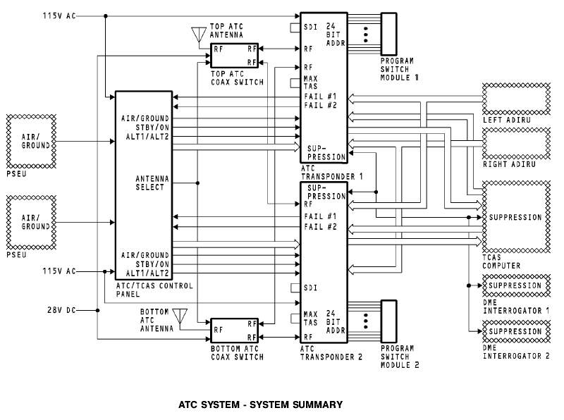
The antenna select circuit makes the transmission signal go to the antenna that receives the strongest interrogation signal.
Test
When you apply power or do a test of the ATC transponder system, the built-in test equipment (BITE) does a check of the operational status of all the internal circuits and for the correct antenna impedance. The BITE circuits identify any failures and put them into the non-volatile memory.
The LEDs on the front panel of the transponder come on to report these conditions:
Transponder status
Antenna status
Transponder control interface status
Altitude interface status.
General
Push the TEST switch on the front of the transponder or select TEST on the ATC/TCAS control panel to start a self-test of the ATC system. During the test, the transponder BITE circuits do these functions:
Normal operation test
Memory tests
Simulated interrogation test of the receiver circuits
Antenna impedance test
TCAS interface test
Valid control and altitude inputs monitor.
Test From the Front Panel
Push and release the test switch. All front panel light emitting diode (LED) status indicators turn red for two seconds. After two seconds, the LRU STATUS turns green and the other LEDs remain red. Then all the LEDs go off for two seconds. At this time, the applicable LEDs come on to show the condition of the ATC transponder system. After 30 seconds, all LEDs go off. These are the LED status indicators and their related conditions:
LRU STATUS (GREEN) - no LRU failures
LRU STATUS (RED) - LRU failure
ANTENNA TOP FAIL - top antenna fails
ANTENNA BOT FAIL - bottom antenna fails
ALTITUDE FAIL - altitude input from the ADIRU fails
CONTROL FAIL - control panel input fails.
Вопросы для самоконтроля.
1. Назначение самолетных ответчиков.
2. Принцип действия самолетных ответчиков.
3. Подавление боковых лепестков.
4. Назначение СО-72М.
5. Состав СО-72М.
6. Основные характеристики СО-72М.
7. Принцип действия.
8. Органы управления и регулировки СО-72М.
9. Включение, проверка функционирования СО-72М.
10. Индикация и сигнализация.
11. Назначение режимов.
12. Какую информацию получает диспетчер в различных режимах.
13.Что индицируется на экране диспетчера при нажатии кнопки «Знак».
14. Что индицируется на экране диспетчера при включении тумблера «Авария».
15. Что означает периодическое мигание лампы «Контроль».
16. Какой код набирается для передачи сообщений об аварийной ситуации, о потере радиосвязи, о нападении на ВС.
17. Назначение шифратора.
18. Назначение дешифратора.
19. Назначение ферритовых вентилей.
20. Назначение блока БПИ-АЦ.
21. Назначение ответвителя с детекторной секцией ОК-02.
22. Назначение приставки бланкирования.
23. Назначение, состав, основные характеристики АТС В737.
24. Принцип работы АТС В737.
25. Интерфейс АТС В737.
26. Включение, проверка функционирования АТС В737.
Рекомендуемая литература.
Основная
1. Сосновский А.А., Хаймович И.А. Радиоэлектронное оборудование летательных аппаратов. Справочник – М.: Транспорт, 1987г.
2. Учебное пособие. Радиоэлектронное оборудование ЛА. Составитель Кукушин В.А. Академия ГА, 2007г.
3. Учебное пособие. COMMUNICATION СВЯЗНОЕ ОБОРУДОВАНИЕ BOEING 737-600/700/800/900. Training Manual. Составитель Кукушин В.А. Академия ГА, 2008г.
4. Учебное пособие. NAVIGATION. Part 1. НАВИГАЦИОННОЕ ОБОРУДОВАНИЕ. Часть 1. BOEING 737-600/700/800/900. Training Manual. Составитель Кукушин В.А. Академия ГА, 2008г.
5. Учебное пособие. COMMUNICATIONS СВЯЗНОЕ ОБОРУДОВАНИЕ
А-320. Training Manual. Составитель Кукушин В.А.
Дополнительная
1. Aircraft Aerodynamic, Structures and Systems. Module 13: M13.04 Communication Navigation (ATA 23/34); M13.06 Equipment and Furnishings (ATA 25) / EASA Part-66 Training Handbook. – LINK&LEARN Aviation Training GmbH, 2007. – 176 p.
2. Эксплуатационная документация на аппаратуру. (Технические описания. Инструкции по эксплуатации. АММ).